Device for rapid large-area preparation of thin film material and setting method

A thin-film material and large-area technology, which is applied in metal material coating process, semiconductor/solid-state device manufacturing, gaseous chemical plating, etc. Wide application and other issues, to achieve the effect of reducing the probability of gas phase nucleation, high gas utilization rate, and increased concentration

Inactive Publication Date: 2008-04-09
NANJING UNIV +1
View PDF0 Cites 22 Cited by
  • Summary
  • Abstract
  • Description
  • Claims
  • Application Information

AI Technical Summary

Problems solved by technology

The disadvantage of the hot wire method is that the uniformity of the film is greatly affected by the geometric structure of the hot wire, and it is difficult to obtain a large-area uniform film material
[0006] It is also possible to provide energy to the reactive gas through various methods such as electron beams and lasers, so that the reactive gas can decompose, react, and form a film, but usually these devices are complex and expensive, and it is difficult to be widely used
[0007] The deposition rate of CVD is also related to the concentration of the local reaction gas near the substrate surface. Increasing the partial pressure of the reaction gas may accelerate the deposition rate of the film. However, when the local concentration of the reaction gas is too high, an undesirable gas phase will appear. reactions and nucleation of solid particles that can deposit on the substrate surface and contaminate the growing film

Method used


Image

  • Device for rapid large-area preparation of thin film material and setting method

Examples


Embodiment Construction

[0019] The specific implementation manner of the present invention will be described below in conjunction with the accompanying drawings.

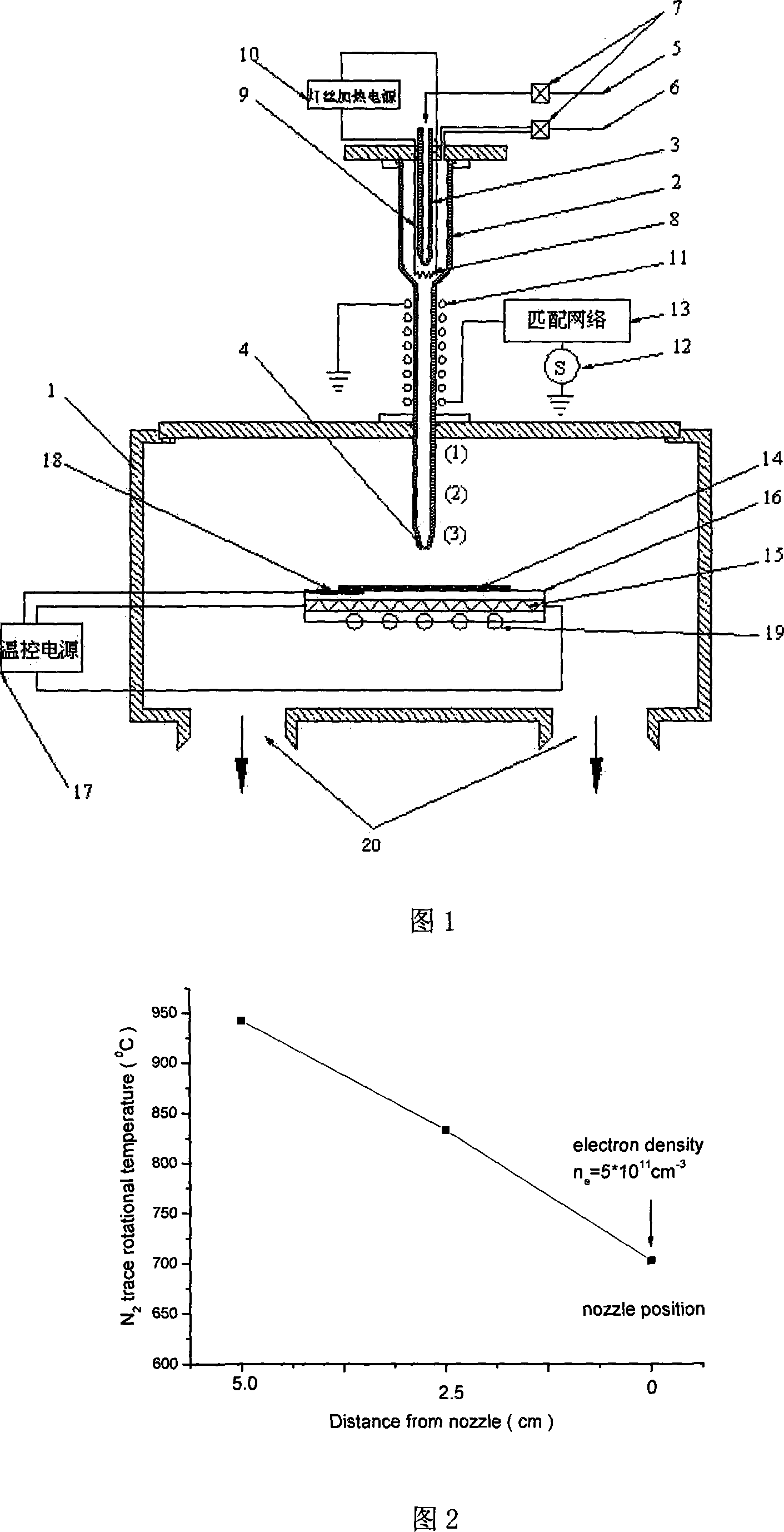
[0020] As shown in Figure 1, the device of the present invention comprises: a vacuum chamber 1, is equipped with vacuum pumping equipment and indoor gas is extracted out by pumping holes 20; A quartz coaxial double nozzle is fixed on the vacuum chamber 1 by a sealing flange, The gas is regulated by the mass flow meter 7 through the pipeline 6 and enters the outer nozzle 2, and is sprayed from the nozzle 4 onto the substrate 14 on the sample stage 16 in the vacuum chamber. The sample stage is driven by a transmission device 19 and can translate in a plane; The inner nozzle 3 is fed with the reaction gas through the pipe 5, and a pair of electrodes 9 are arranged on the outside thereof, connected to the hot wire power supply 10 and the metal hot wire 8 at the outlet of the inner nozzle; the outer wall of the outer nozzle is surrounded by a wa...


PUM


Abstract

The invention relates to a thin film material preparation device. The invention seals two to four spray pipes which are used for admitting feed gas and fixed on an admitting sediment cavity. The admitting sediment cavity is arranged on a vacuum sediment cavity. The reacting gas or shipping gas is admitted into the spray pipes through air source. A heating wire is arranged around a spout exit of the spray pipes. An inductance coil driven by power supply is provided on an outer wall of the spray pipes. The inductance coil can generate a plasma body. A through sole platform for growing film is provided in the sediment cavity. A rarefying exit pipe is arranged at the lower part or the lower side part of the sediment cavity. The thin film material preparation device of the invention has the advantages of high film forming quality, high rate of sedimentation, low growing temperature and high gas efficiency and so on.

Description

technical field [0001] The invention relates to a device and a setting method for preparing thin film materials, and relates to equipment for preparing semiconductor functional materials, amorphous silicon and polysilicon thin film materials for solar cells, in particular to a device and a setting method for rapidly and large-area preparation of thin film materials. Background technique [0002] Semiconductor functional materials such as Si, Ge, GaN, and GaAs are widely used, and the prepared high-quality thin film materials have more and more development potential in microelectronics, optoelectronics, and solar energy conversion. [0003] Among the developed thin film preparation methods and equipment, chemical vapor deposition (CVD) is a commonly used method of thin film deposition. Film-on-bottom technology. A typical CVD process includes the following steps: (1) The reactive gas is introduced into the reaction chamber and is dissociated or excited to generate reactive r...

Claims


Application Information

Patent Timeline
Patent Type & Authority Applications(China)
IPC IPC(8): C23C16/50H01L21/205H01L21/365
Inventor 施毅左则文辛煜濮林王军转张荣韩平谢自立顾书林郑有炓
Owner NANJING UNIV
Why Eureka
Try Eureka