Method for forming grounding via hole between gallium nitride device and circuit

A gallium nitride device, gallium nitride technology, applied in circuits, electrical solid state devices, semiconductor devices, etc., can solve problems such as inability to etch, achieve the effects of eliminating parasitic inductance, easy implementation, and simple operation

Inactive Publication Date: 2008-07-23
NO 55 INST CHINA ELECTRONIC SCI & TECHNOLOGYGROUP CO LTD
View PDF0 Cites 30 Cited by
  • Summary
  • Abstract
  • Description
  • Claims
  • Application Information

AI Technical Summary

Problems solved by technology

[0015] High-density plasma etching of GaN materials has also been widely studied. Since the plasma of fluorine-based gases reacts with GaN to generate low-volatility substances, it cannot be etched effectively, while the plasma of chlorine-bas

Method used


Image

  • Method for forming grounding via hole between gallium nitride device and circuit
  • Method for forming grounding via hole between gallium nitride device and circuit
  • Method for forming grounding via hole between gallium nitride device and circuit

Examples


Embodiment 1

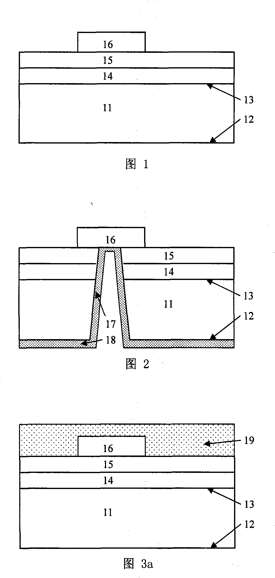
[0049] Shown in Fig. 1 is the aluminum gallium nitride / gallium nitride heterojunction material on the SiC substrate that is used for etching through hole in the present invention and device or circuit on it (for simplicity, only draw an electrode ), which includes a SiC substrate 11 with a surface 12 and a surface 13, a gallium nitride buffer layer 14 on the SiC substrate surface 13 and an aluminum gallium nitride barrier layer 15 formed thereon, and a barrier An electrode 16 is formed on layer 15 . The thickness of the substrate 11 is generally 300-500 μm, the thickness of the GaN buffer layer 14 is generally 1-3 μm, and the thickness of the AlGaN barrier layer 15 is 15-30 nm.

[0050] The surface of the epitaxial layer and the electrode 16 in FIG. 1 are coated with a polymer 19, as shown in FIG. 3a, the role of the polymer 19 is to protect the underlying device or circuit from being damaged in the subsequent process on the one hand, On the other hand, it also makes the surf...

Embodiment 2

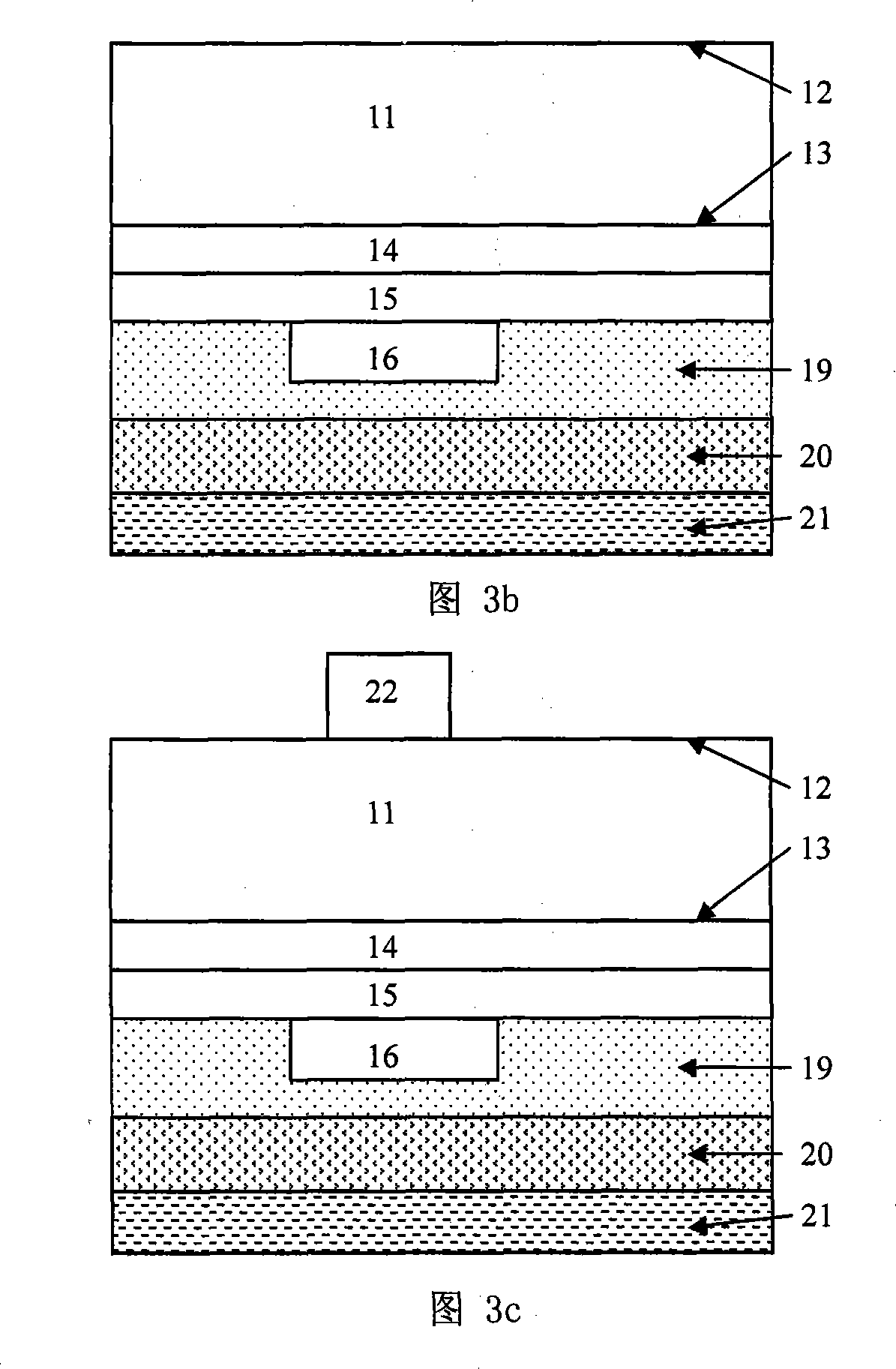
[0063] Referring to Figures 3a-3b, firstly the surface of the substrate 11 is coated with a polymer 19 to protect the device or circuit thereon, then it is installed upside down on the pressure plate 21, and filled with an adhesive 20, and then the lining The thickness of the bottom 11 is reduced to between 50-100 μm. The specific implementation of this process is the same as in Embodiment 1, and will not be described in detail here.

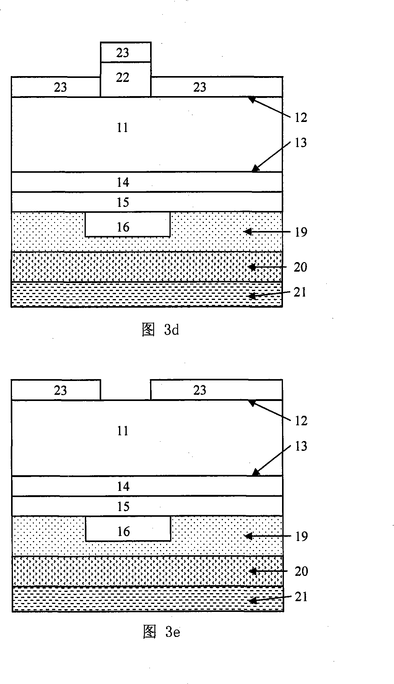
[0064] After the substrate 11 is thinned, a metal photolithography mark is made on it, and the function of the photolithography mark is to facilitate the photolithography alignment in the subsequent process. The preferred photolithographic mark formation process in this embodiment includes coating photoresist on the surface 12 of the substrate 11, exposing and developing the photolithographic mark on the mask with ultraviolet light. The mark pattern is transferred onto the photoresist, and then the Ti / Au is evaporated by electron beam and lifted...


PUM

PropertyMeasurementUnit
Thicknessaaaaaaaaaa
Thicknessaaaaaaaaaa
Thicknessaaaaaaaaaa

Abstract

The invention provides a process for forming gallium nitride device and ground through-hole in circuit, which comprises the following steps including (a) coating polymeric substance on the surface of epitaxy material of heterojunction of gallium aluminum nitride/ gallium nitride, (b) installing the surface coated polymeric substance on a pressing disc, (c) ball milling, polishing and catching the surface 12 of an underlay, (d) coating a thickness of mask layer on the surface of the underlay, a trompil with precalculated position is arranged in the mask layer 23, (e) etching the underlay to obtain the through hole by employing jigger coupling plasmas of fluoride group gas, (f) reserving the mask layer, etching to form ground through-hole of the electrode by the jigger coupling plasmas of fluoride group gas and (g) removing the mask layer, metalizing the surface of the through-hole and underlay and finally realizing the ground connection of the electrode. The invention saves using ground lead, eradicates the unwilled stray inductance capable lead in micro frequency, further, the operation is simple, which is easy to realize in technique.

Description

technical field [0001] The invention relates to a method for forming ground vias in semiconductor devices and circuits, in particular to a method for forming ground vias in gallium nitride devices and circuits on a silicon carbide substrate. Background technique [0002] At present, the use of semiconductor solid-state devices in microwave systems can effectively reduce the size of the system and improve reliability. With the development of science and technology, various microwave application systems urgently need electronic devices suitable for high temperature, high frequency, high power, and radiation resistance. All aspects are greatly restricted, so it is necessary to find new semiconductor materials to replace Si and GaAs. Gallium nitride (GaN) is a new type of wide-bandgap semiconductor material, which is characterized by a wide bandgap (the bandgap width is 3.4eV), high electron mobility and saturation velocity (the electron mobility in the bulk material can reach ...

Claims


Application Information

Patent Timeline
IPC IPC(8): H01L21/60
CPCH01L2924/0002H01L21/76898H01L2924/00
Inventor 任春江陈堂胜焦刚陈辰
Owner NO 55 INST CHINA ELECTRONIC SCI & TECHNOLOGYGROUP CO LTD
Why Eureka
Try Eureka