Air backheating type mine gas separation and liquefaction method and apparatus

A gas and heat recovery technology, applied in the field of gas separation and liquefaction, can solve the problem of high energy consumption, and achieve the effects of high energy consumption, simple manufacturing process, and simple structure

Inactive Publication Date: 2008-09-24
北京国能时代能源科技发展有限公司 +1
View PDF4 Cites 17 Cited by
  • Summary
  • Abstract
  • Description
  • Claims
  • Application Information

AI Technical Summary

Problems solved by technology

However, since the above-mentioned processes all need to separate nitrogen at low temperature, the energy consumption required by the process equipment is still relatively high

Method used


Image

  • Air backheating type mine gas separation and liquefaction method and apparatus
  • Air backheating type mine gas separation and liquefaction method and apparatus
  • Air backheating type mine gas separation and liquefaction method and apparatus

Examples


Embodiment 1

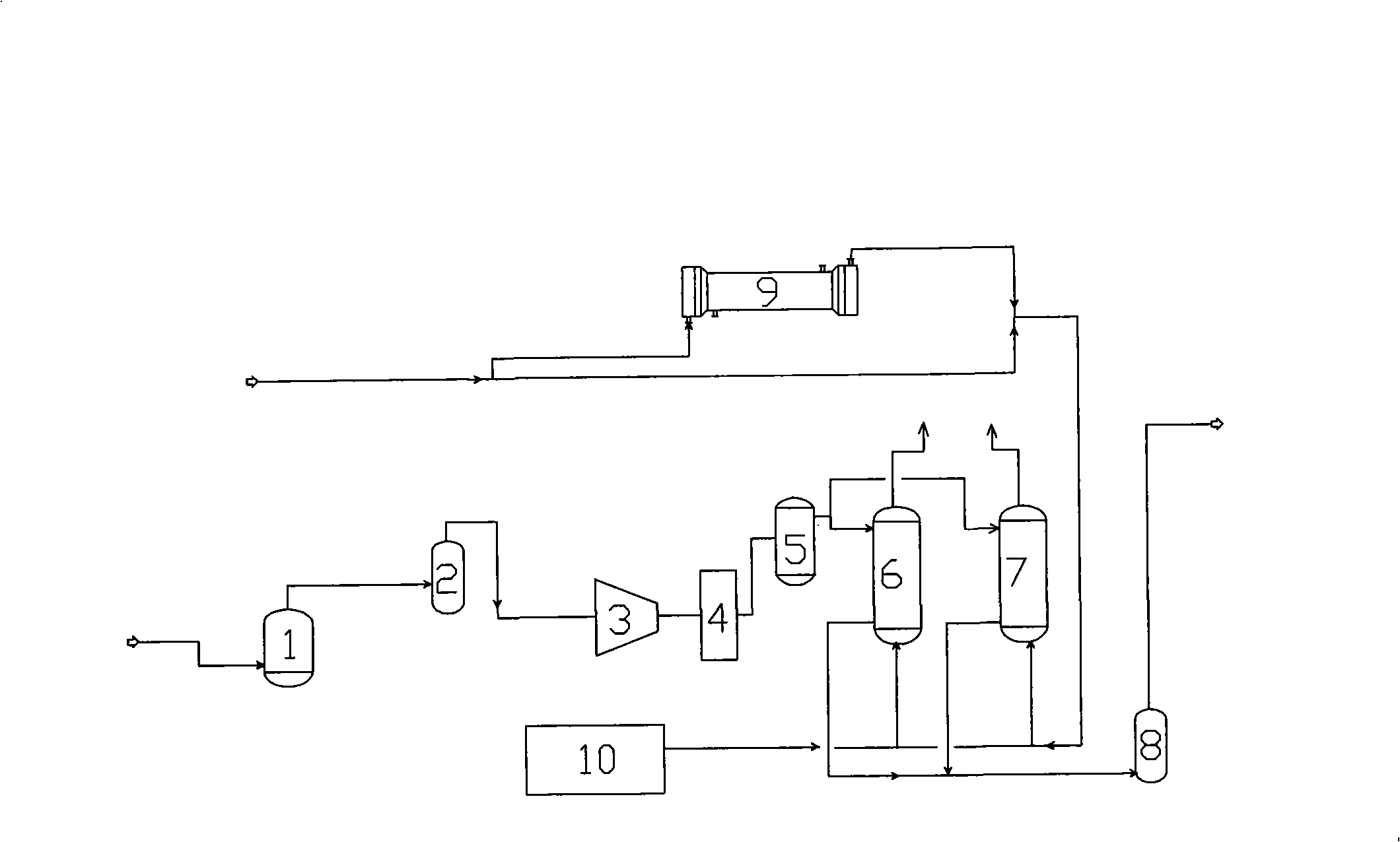
[0041] see figure 1 , is a schematic diagram of the compression purification equipment in Example 1 of the present invention. Including filter 1, gas-liquid separator 2, compressor 3, cooler 4, gas-liquid separator 5, molecular sieve purification equipment group, the molecular sieve purification equipment group includes two molecular sieve dryers 6, 7, when the first one When the molecular sieve dryer 6 is in operation, the second molecular sieve dryer 7 is heated for regeneration, cooled for standby, and switched every 12 hours. The molecular sieve drying equipment is mainly used to remove water and carbon dioxide. There is a filter 8 and a heater 9 behind the molecular sieve equipment group. In addition, there is a pressure swing adsorption nitrogen generator 10 to provide nitrogen for replacing the gas in the purification equipment.

[0042] Figure 4 Shown is the overall process flow diagram of the method for separating and liquefying mine gas using the air recuperatio...

Embodiment 2

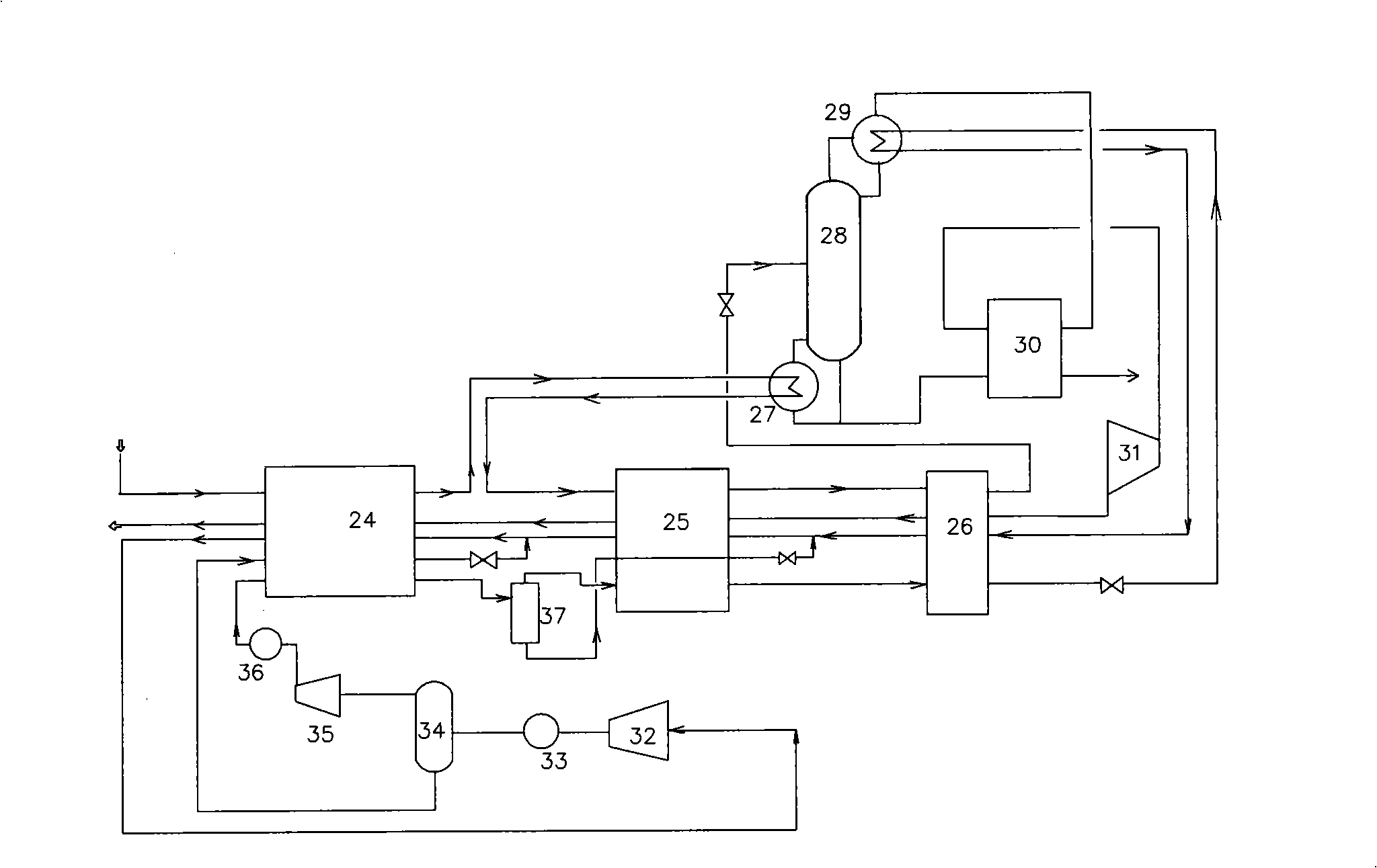
[0064] see image 3 , is a schematic diagram of the refrigeration equipment and the liquefaction separation equipment in Example 2 of the present invention. The heat exchanger and fractionation tower for separating the liquefied part are basically the same as those in Example 1, and the description will not be repeated. The difference is that the feed gas is first cooled to 0°C to -50°C through the heat exchanger 24, and then passes through the evaporator 27 at the bottom of the fractionation tower to provide heat for the evaporator, while the feed gas itself is pre-cooled. Therefore, on the equipment, the heating pipeline of the evaporator 27 of the fractionation tower is connected with the raw material gas pipeline, and then the raw material gas is cooled to -150℃~-180℃ through the heat exchangers 25 and 26, so that most of the mine gas is It is cooled to a liquid and then enters the middle of the fractionation column 28 . Another difference is that the refrigeration syste...


PUM


Abstract

The invention relates to a mine gas separation liquefaction method and a device. The technical proposal of the method is that raw mine gas is compressed and purified, the impurities are removed to produce compressed purified mine gas; the compressed purified mine gas is inlet into a heat exchanger to be cooled to below 82.5 degree centigrade below zero; the cooled mine gas is inlet into the middle part of a fractionating tower, wherein the bottom part of the fractionating tower is provided with an evaporator, the top is provided with a condenser; the top of the fractionating tower produces low temperature air of high purity, while the bottom of the fractionating tower produces high purity liquefied natural gas; the low temperature air separated at the top of the fractionating tower is inlet into the heat exchanger to be used as the cold energy source. The method and the device of the invention avoids production process of nitrogen at low temperatures and adopts the method of air recycling, thereby the structure is simple, the cost and the energy consumption are reduced, and the device and the method are more conducive to wide popularization.

Description

technical field [0001] The invention relates to a gas separation and liquefaction method and equipment, in particular to an air recuperation type mine gas separation and liquefaction equipment and method. Background technique [0002] The coalbed methane extracted during the coal mining process is mine gas. Because of its low pressure and low methane content, it is mixed with air, which brings difficulties to the processing and transportation of this gas. It is usually discharged into the atmosphere. This not only caused serious air pollution, but also caused a great waste of resources. If the coalbed methane (mainly methane) in this gas is separated from the air and the purified coalbed methane is liquefied, it will make transportation and utilization very convenient. [0003] Conventional separation methods include absorption method, adsorption method, membrane permeation method and cryogenic rectification method. In the previous methods, the purity of separation is diff...

Claims


Application Information

Patent Timeline
Patent Type & Authority Applications(China)
IPC IPC(8): F25J3/02
Inventor 张俐惠
Owner 北京国能时代能源科技发展有限公司
Why Eureka
Try Eureka