
Drive device with electric furl

A technology of driving device and electric coil, which is applied in the direction of electromechanical device, transmission device, gear transmission device, etc.

Active Publication Date: 2010-09-29
SAN HSIN PLASTECH
View PDF4 Cites 0 Cited by
  • Summary
  • Abstract
  • Description
  • Claims
  • Application Information

AI Technical Summary

Problems solved by technology

[0003] When using an induction motor as a driving device, since the induction motor must use more manufacturing materials, such as silicon steel sheets and induction coils, the manufacturing cost is relatively high and the volume is relatively small large and heavy
On the other hand, the induction motor will produce relatively high rotor copper loss and high noise during operation, and the torque performance at low speed operation is also insufficient. bad
On the other hand, the induction motor cannot immediately stop at the predetermined position when the power is cut off, and the design of the brake structure must be added, which increases the manufacturing cost and the trouble of assembly.
[0004] In addition, when using a brushed DC motor as the drive device, since the brushed DC motor has carbon brushes and commutators, the carbon brushes continuously grind the commutator, causing carbon brush pollution
The sparks generated by the carbon brush when it leaves the commutator will cause electromagnetic interference, which will interfere with other electronic equipment, and the carbon brush and commutator are easy to wear out, requiring more maintenance time and cost

Method used

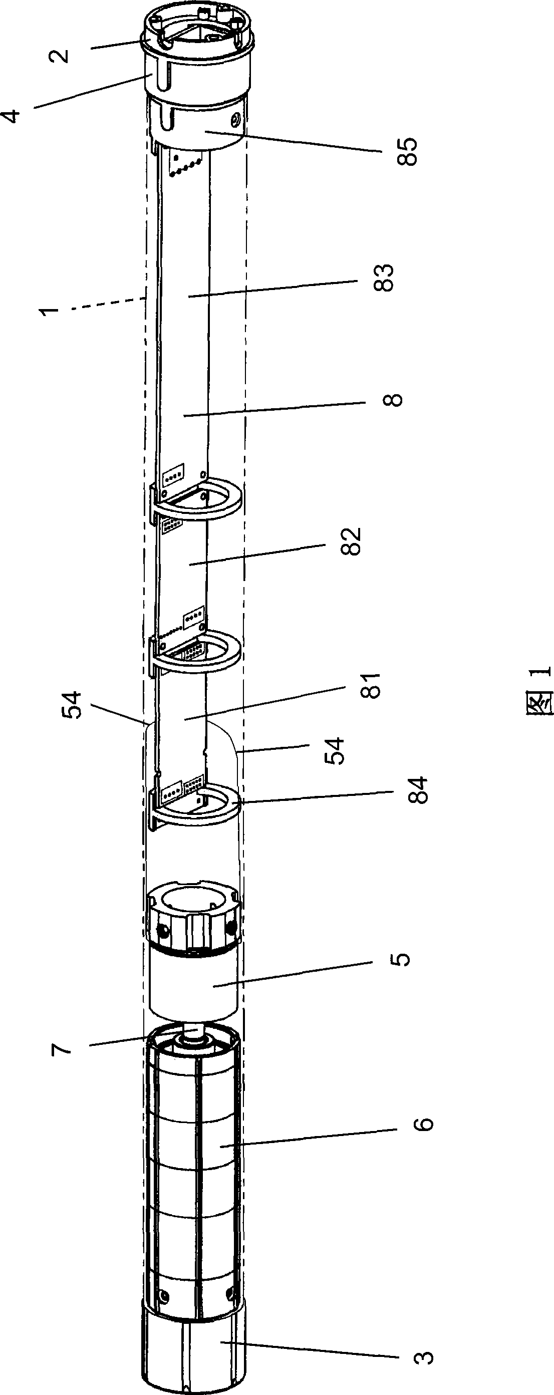
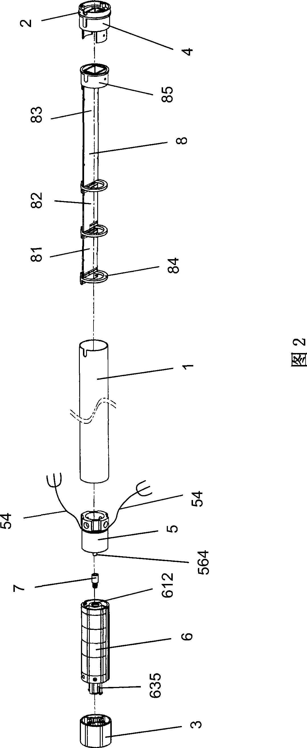
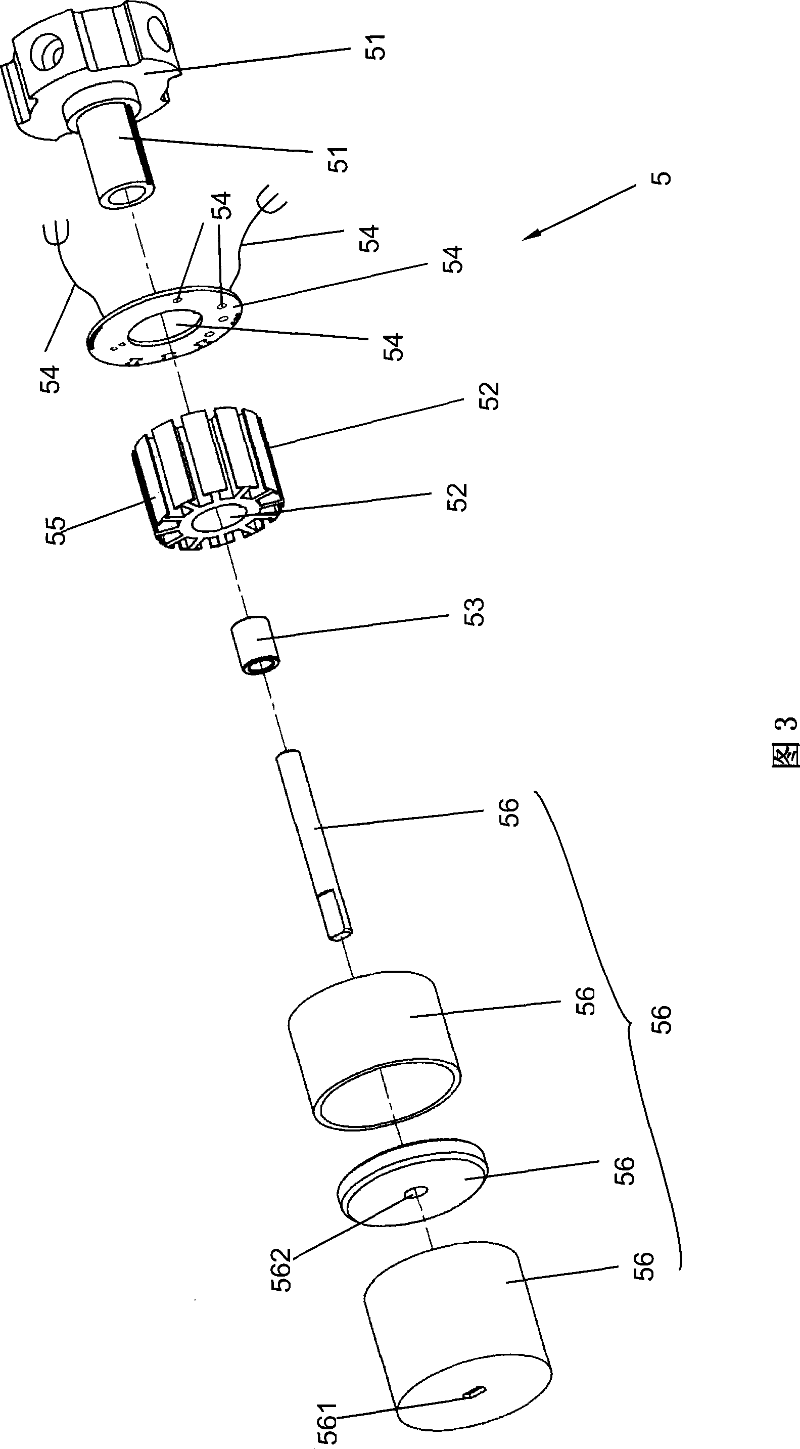

Image

  • Drive device with electric furl
  • Drive device with electric furl
  • Drive device with electric furl

Examples


Embodiment Construction

[0079] Such as figure 1 and figure 2 As shown, the present invention provides a driving device with electric retraction, which includes a housing 1, a motor tube end cover 2, a transmission wheel 3, a crown ring 4, a permanent magnet DC brushless motor 5, a speed reducer Machine 6, a power transmission assembly 7 and a driving machine 8, the housing 1 is a hollow tubular body with two ends open, the permanent magnet brushless DC motor 5, the reducer 6, the power transmission assembly 7 and the drive The motors 8 are all located in the housing 1, and the crown ring 4 is sleeved on the outer peripheral wall of the motor tube end cover 2. The motor pipe end cover 2 is connected with the driving machine 8 , and the transmission wheel 3 is connected with the casing 1 and the reducer 6 .

[0080] Such as image 3As shown, the permanent magnet brushless DC motor 5 includes a base 51, a stator 52, a bearing 53, a circuit board 54, a plurality of induction coils 55 and a rotor 56,...


PUM


Abstract

A driving device with an electric retracting device comprises a shell body, a permanent magnet DC brushless motor, a reducer, a power transmission component and a driving machine. The permanent magnet DC brushless motor, the reducer and the power transmission component are arranged in the shell body. Two ends of the power transmission component are respectively connected with the permanent magnetDC brushless motor and the reducer. The driving machine is electrically connected with the permanent magnet DC brushless motor. Owning to the design, the driving device is helpful to realize the efficacies of miniaturization, lightweight, strong bearing capacity, saving energy, low copper loss, no spark and low noises.

Description

technical field [0001] The present invention relates to a driving device with electric retraction, more specifically, the structural improvement of the driving device for the electric retraction mechanism. Background technique [0002] In daily life, many products have retracting mechanisms, such as Roman blinds, horizontal venetian blinds, projection screens, and iron rolling doors. With the rapid development of technology, consumers have higher requirements for the quality of life. Many retracting mechanisms that used manpower in the early stage have been gradually replaced by electric retracting mechanisms. The current electric retracting mechanisms all use induction motors or DC motors. A brush motor is used as the drive unit. [0003] When an induction motor is used as a driving device, since the induction motor must use more manufacturing materials, such as silicon steel sheets and induction coils, the manufacturing cost is relatively high, and the volume and weight a...

Claims


Application Information

Patent Timeline
Patent Type & Authority Patents(China)
IPC IPC(8): H02K29/00H02K7/116H02K5/16H02K11/00F16H1/28F16H3/44E06B9/72H02K11/33
Inventor 黄淑媛
Owner SAN HSIN PLASTECH
Learn More