Method for welding stainless steel thin walled pipe circular seam joint and device

A welding method and welding device technology, applied in the field of stainless steel thin-walled pipe welding engineering, to achieve the effects of reducing harsh requirements, precise control of penetration depth, reliable welding method and welding equipment

Inactive Publication Date: 2009-01-21
CHONGQING UNIV
View PDF2 Cites 15 Cited by
  • Summary
  • Abstract
  • Description
  • Claims
  • Application Information

AI Technical Summary

Problems solved by technology

[0004] In view of the above-mentioned deficiencies existing in the existing welding technology, the purpose of the present invention is to provide a stainless steel that reduces welding defects, especially reduces the sensitivity of joint welding cracks, reduces costs, breaks through ordinary welding technology that cannot meet joint performance requirements, and improves welding quality. Welding Method of Thin-wall Pipe Circumferential Seam Joint

Method used


Image

  • Method for welding stainless steel thin walled pipe circular seam joint and device
  • Method for welding stainless steel thin walled pipe circular seam joint and device
  • Method for welding stainless steel thin walled pipe circular seam joint and device

Examples


Embodiment 1

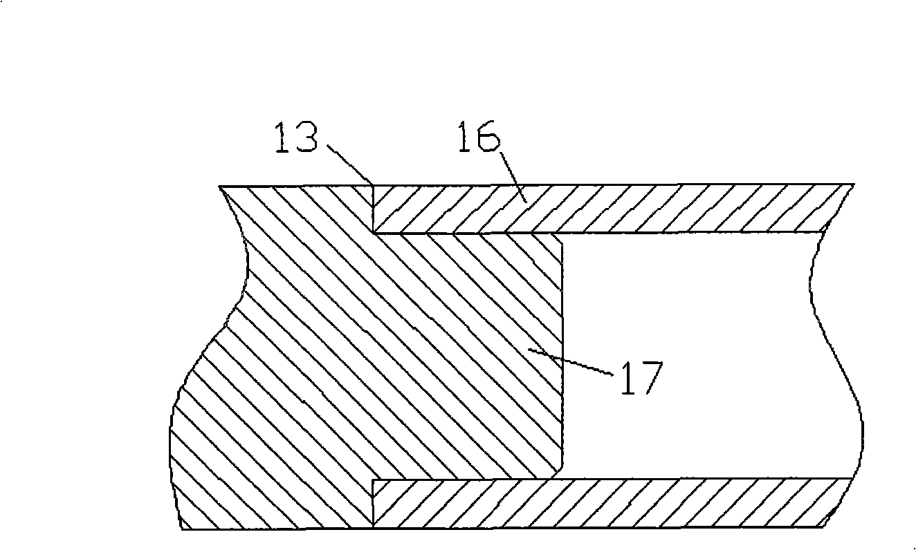
[0063] see image 3 or Figure 4 , Welding of thin-walled pipe fittings of austenitic stainless steel 0Cr18Ni10Ti with a wall thickness of 0.4-0.8mm and an outer diameter of 8-12mm with solid end plugs or ring seam joints of thick-walled ends, cleaning the welded joints, removing oxides, flying Dust, oil and other impurities, keep the joint clean and dry; the welding process parameters are: pulse peak welding current: 45 ~ 75A, pulse base value welding current: 5 ~ 12A, welding pulse frequency: 15 ~ 25Hz, argon flow: 8~12l / min, tungsten pole diameter: 1.2~2.4mm, excitation current: 2~10A, excitation frequency: 3~20Hz, welding speed: 2~10s / week.

Embodiment 2

[0065] see image 3 Welding of the thin-walled pipe fittings of Zr-4 pick alloy with a wall thickness of 0.6-0.9mm and an outer diameter of 6-15mm and the annular seam joint of the solid end plug, cleaning the welded joint, and removing oxides, flying dust, oil stains and others Impurities, keep joints clean and dry; the welding process parameters are: pulse peak welding current: 50-80A, pulse base value welding current: 8-20A, welding pulse frequency: 10-30Hz, argon flow: 12-20l / min , Tungsten pole diameter: 2.0~3.2mm, excitation current: 4~15A, excitation frequency: 5~20Hz, welding speed: 4~15s / week.

Embodiment 3

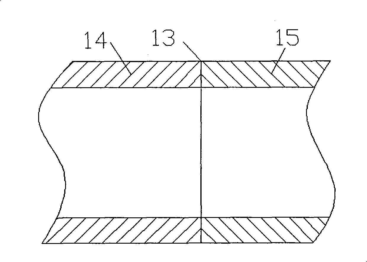
[0067] see figure 2 , the welding of the circular seam joint between two thin-walled pipe fittings of magnesium alloy AZ61 with a wall thickness of 0.7-1.0mm and an outer diameter of 6-10mm, clean the welded joint, remove oxides, fly dust, oil and other impurities, and maintain The joints are clean and dry; the welding process parameters are: square wave AC welding current: 60-100A, argon flow: 8-20l / min, tungsten pole diameter: 1.2-3.2mm, excitation current: 3-12A, excitation frequency: 4~16Hz, welding speed: 3~12s / week.


PUM


Abstract

The invention provides a welding method of a joint of a circular seam of a stainless steel thin-wall pipe, which comprises the following steps: a work part holding and rotating mechanism is adopted to carry out holding on the joint of the work part of the stainless steel thin-wall pipe; the joint of the work part of the stainless steel thin-wall pipe is positioned in an air chamber and can rotate; the technology of non-melt electrode pulse gas shielding arc welding which is controlled by applied magnetic field is adopted to carry out welding on the joint of the circular seam of the stainless steel thin-wall pipe; the invention also provides a welding device of the joint of the circular seam of the stainless steel thin-wall pipe, which comprises a work part holding and rotating mechanism, a centre, a welding torch, an air sifter, an air chamber and an excitation device of the applied magnetic field; the applied electromagnetic field is generated in the welding joint area so as to realize the welding process of electromagnetic stirring. The method and the device of the invention realize the welding with good quality, high efficiency, low cost and high stability of the joint of the circular seam of the thin-wall pipe made of various materials such as stainless steel, pick and alloy thereof, magnesium alloy and aluminium alloy.

Description

technical field [0001] The invention relates to the field of welding engineering of stainless steel thin-walled pipes, in particular to a welding method and device for girth weld joints of stainless steel thin-walled pipes. Background technique [0002] Stainless steel thin-walled tubes are widely used in metallurgy, chemical industry, food, aerospace, aviation, nuclear industry and other fields, and their thickness is generally less than 3mm. Due to the large linear expansion coefficient and small thermal conductivity of stainless steel, and the thin wall thickness of thin-walled tubes, stainless steel thin-walled tubes, especially austenitic stainless steel thin-walled tubes, are often welded with ordinary non-melting inert gas protection. Defects such as welding deformation, welding cracks, pores, inclusions, and incomplete penetration will occur, especially in some aerospace and nuclear industries that require high performance. These defects are not allowed, so a lot of ...

Claims


Application Information

Patent Timeline
IPC IPC(8): B23K9/167B23K9/235B23K9/12B23K9/095
Inventor 罗键王颖
Owner CHONGQING UNIV
Why Eureka
Try Eureka