Fiber-optic scanning head and driving method thereof

An optical fiber scanning and optical fiber technology, applied in medical science, diagnosis, endoscopy, etc., can solve the problems of low imaging signal-to-noise ratio and impact on imaging quality, achieve convenient coupling, increase line scanning range, and simple manufacturing method Effect

Inactive Publication Date: 2009-06-03
HUAZHONG UNIV OF SCI & TECH
View PDF1 Cites 31 Cited by
  • Summary
  • Abstract
  • Description
  • Claims
  • Application Information

AI Technical Summary

Problems solved by technology

However, the scanning trajectory of the probe is a Lissajous figure, and the signal-to-noise rat

Method used


Image

  • Fiber-optic scanning head and driving method thereof
  • Fiber-optic scanning head and driving method thereof
  • Fiber-optic scanning head and driving method thereof

Examples


Example Embodiment

[0053] Embodiment 1: Fabrication of optical fiber scanning probe. Proceed as follows

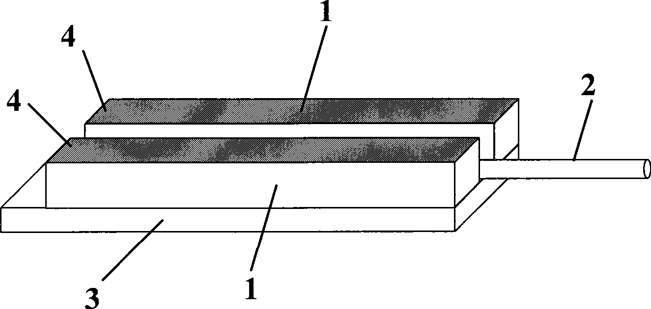
[0054] 1. Take two piezoelectric ceramic sheets 2 with a length of 50mm, a width of 0.2mm, and a thickness of 0.2mm with electrode layer 1 plated on one side, and take a thin copper sheet 3 with a thickness of 53mm in length, 0.6mm in width and 0.1mm in thickness. One piece, two piezoelectric ceramic sheets 2 are glued on the copper sheet 3 in parallel with epoxy resin, one end of the piezoelectric ceramic sheet 2 is flush with the end of the copper sheet 3, and the distance between the two piezoelectric ceramic sheets 2 is 0.2mm.

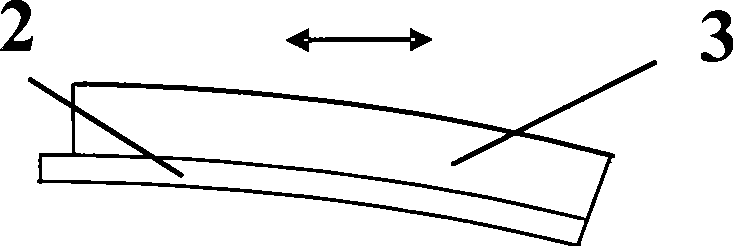
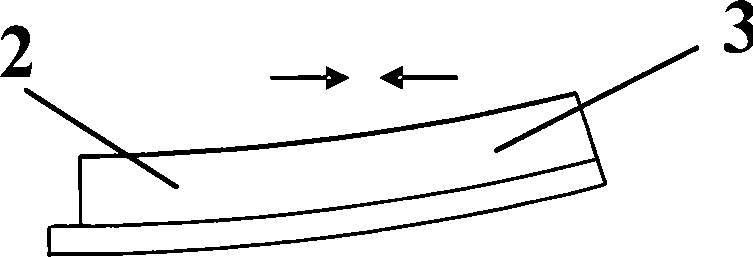
[0055] 2. Remove the 30-40mm coating from the end of a single-mode fiber to expose the bare fiber 4. Use a fiber cleaver to cut the fiber end face evenly. Place the fiber 4 in the gap between the two piezoelectric ceramic sheets, and reserve a length of 10mm. (Resonance frequency is about 1KHz) As the free end of vibration, the optical fiber 4 is firmly bonded to the...

Example Embodiment

[0059] The second embodiment: the optical fiber scanning probe is used to form an endoscopic fluorescence imaging system. The schematic diagram of the endoscopic fluorescence imaging system is as Picture 9 Shown.

[0060] 1. After the optical fiber scanning probe is fabricated as in the first step of the embodiment, it is sleeved into a stainless steel tube 6 with a diameter of 2 mm. A micro convex lens 7 is pre-installed at one end of the stainless steel tube 6 for focusing the light emitted from the optical fiber and collecting fluorescence.

[0061] 2. Adjust the position of the optical fiber scanning probe in the stainless steel tube 6 so that the optical axis of the optical fiber coincides with the optical axis of the lens 7, and adjust the optical fiber 4 and the lens 7 to a proper distance, then use epoxy resin 8 to connect the lead end of the optical fiber probe to the stainless steel tube 6 Glue together.

[0062] 3. Put the signal lead of the optical fiber and the probe...


PUM

PropertyMeasurementUnit
Thicknessaaaaaaaaaa

Abstract

The invention relates to a fiber-optic scanning head and the driving method thereof. The fiber-optic scanning head is characterized in that two piezoelectric ceramic pieces plated with electrode layers are symmetrically and parallelly spliced on a thin conductive substrate which is free from inverse piezoelectric effect; a section of bare optical fiber, which is free from coating layer at the tail end and is provided with a suitable structure on the end surface and is spliced between the two piezoelectric ceramic pieces; a bare optical fiber in appropriate size is reserved, so as to be served as a vibration free end; the electrods of the two piezoelectric ceramic pieces have access to driving signals; the driving signals are formed by the superposition of a sawtooth wave and a sine wave; the sawtooth wave ensures that an identical elongation or shortening amount are produced by two piezoelectric ceramic pieces at the same time, so that position of the fiber-optic end is driven to move, and the field scanning action is finished; the sine wave ensures that a tiny length difference is produced by the two piezoelectric ceramic pieces, so as to produce a slight swing which is parallel to the thin conductive substrate, the optical fiber enables to produce a resonance with a greater amplitude, and the line scanning action can be finished. The fiber-optic scanning head has the advantages that the structure is simple, and the volume of the probe is reduced effectively. Therefore, the scanning of the probe is more stable, and the phenomenon of the non-uniform imaging quality is eliminated.

Description

technical field [0001] The invention belongs to the technical field of optical scanning imaging, in particular to an optical fiber scanning probe and a driving method thereof. Background technique [0002] Optical imaging can not only realize non-invasive, non-invasive, non-ionizing radiation and real-time detection and imaging of living tissues, but also can be used for structural analysis of living biological tissues, measurement of characteristic parameters, and diagnosis and treatment of diseases, and its development momentum is rapid. In order to better observe the structure of biological tissue, optical scanning technology came into being. Representative optical scanning imaging techniques include optical coherence tomography (Optical Coherence Tomography), confocal microscopy imaging, and two-photon excited fluorescence imaging. Optical coherence tomography has excellent characteristics such as fast imaging and high resolution, and is of great significance to biologi...

Claims


Application Information

Patent Timeline
IPC IPC(8): A61B1/07A61B5/00
Inventor 骆清铭刘志海曾绍群付玲
Owner HUAZHONG UNIV OF SCI & TECH
Why Eureka
Try Eureka