
Method of bonding resins by light irradiation and process for producing resin article

A technology of bonding method and manufacturing method, which is applied in the field of resin bonding based on light irradiation and the manufacture of resin parts, can solve flow path blockage, difficult microchip manufacturing method, difficulty in coping with narrow flow path width and flow path pattern Complications and other problems, to achieve the effect of suppressing deformation, suppressing the blockage of the flow path, and facilitating the narrowing of the flow path width

Inactive Publication Date: 2009-07-29
ALPS ALPINE CO LTD
View PDF3 Cites 11 Cited by
  • Summary
  • Abstract
  • Description
  • Claims
  • Application Information

AI Technical Summary

Problems solved by technology

However, the method of Document 2 is only a method for bonding PDMS substrates containing Si-O bonds and having a strong affinity with silicon oxide films, and it is impossible to achieve bonding between resin substrates other than PDMS substrates. bonding
[0013] In the methods of Documents 3 and 4, it is necessary to apply a resin composition to the surface of the substrate, and it is difficult to directly apply this method to a microchip manufacturing method due to the occurrence of clogging of the flow path.
As in Document 1, it is conceivable to apply the resin composition while avoiding the flow path. However, as mentioned above, such a coating process is not only a factor that reduces the productivity of microchips, but it is also difficult to cope with the narrowing of the flow path width. Complicated with the flow pattern

Method used


Image

  • Method of bonding resins by light irradiation and process for producing resin article
  • Method of bonding resins by light irradiation and process for producing resin article
  • Method of bonding resins by light irradiation and process for producing resin article

Examples


Embodiment 1

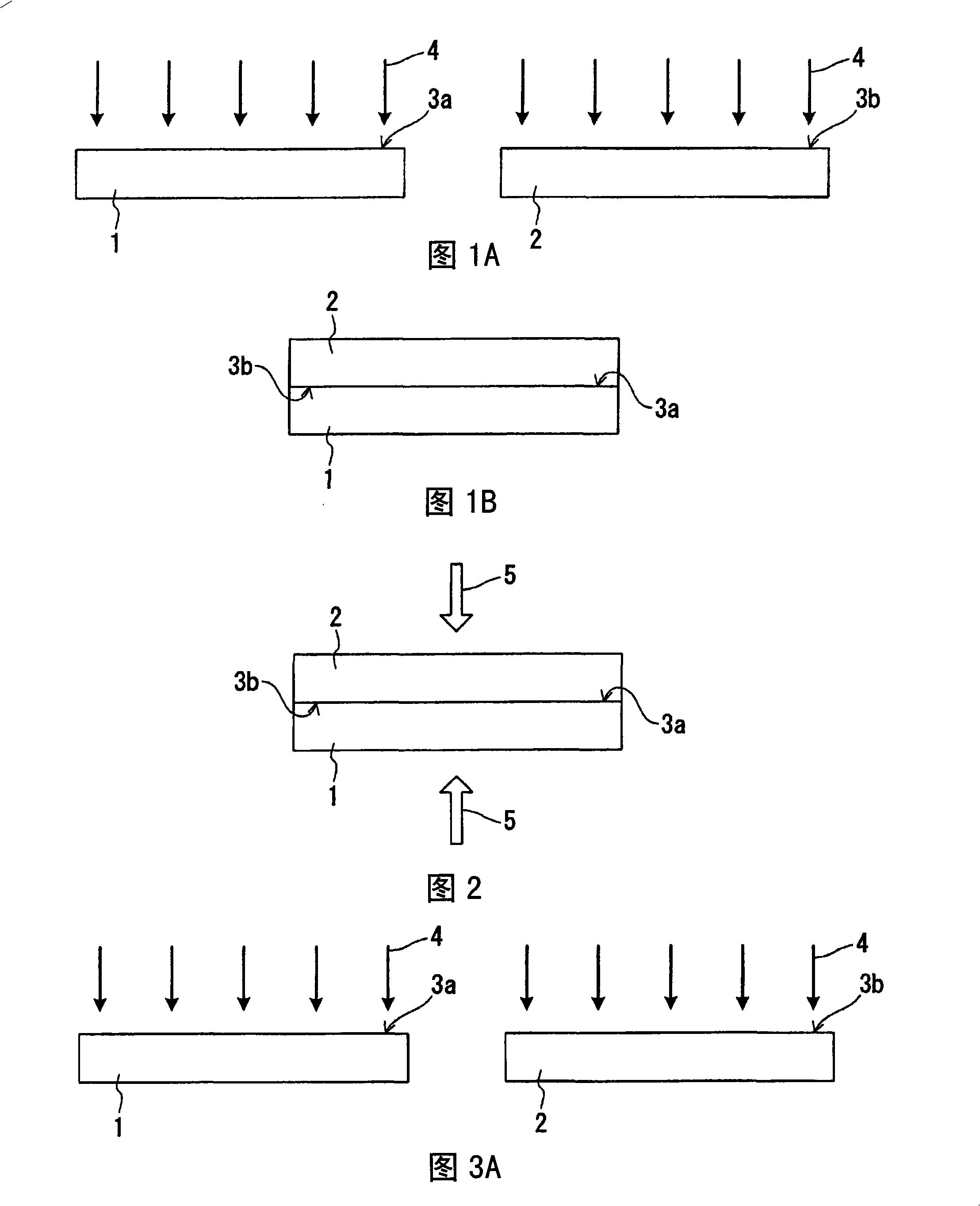
[0075] Using a Xe excimer lamp (manufactured by Usio Electric, UER20-172A), each of a pair of resin substrates (70mm×20mm, thickness 2mm) composed of a cycloolefin polymer (ZEONEX330R manufactured by Nippon Zeon Co., Ltd., glass transition temperature 123°C) The surface is irradiated with ultraviolet light (wavelength 172nm). The irradiation of ultraviolet light is carried out in the atmosphere, the distance between the lamp and the surface of the substrate is 5mm, and the irradiation intensity is 10mW / cm 2 , The irradiation time is 10 minutes. The irradiated surface of ultraviolet light is the whole of one main surface of each substrate.

[0076] When X-ray excitation photoelectron spectroscopy (XPS) measurement was performed on the substrate surface (irradiated surface) before and after ultraviolet light irradiation, it was found that the signal derived from oxygen in the Ols spectrum increased significantly after irradiation compared with before ultraviolet light irradiati...

Embodiment 2

[0083] In the same manner as in Example 1, ultraviolet light was irradiated to the respective surfaces of a pair of resin substrates made of a cycloolefin polymer used in Example 1.

[0084] Next, N-(2-aminoethyl)-3-aminopropyltrimethoxysilane (AEAPS), which is a kind of aminosilane as a silane coupling agent, is applied to the irradiated surface of one resin substrate (resin substrate A). . On the other hand, 3-glycidyl ether aminopropyl trimethoxysilane (GPS) having an epoxy group as a terminal group was applied to the irradiated surface of another resin substrate (resin substrate B). The following formulas (1) and (2) represent the structural formulas of AEAPS and GPS.

[0085] [chemical formula 1]

[0086]

[0087] [chemical formula 2]

[0088]

[0089] Resin substrates A and B surface-treated with a silane coupling agent are opposed in such a way that the respective irradiated surfaces (surface-treated surfaces) are in contact with each other, and a pressure of 0...


PUM


Abstract

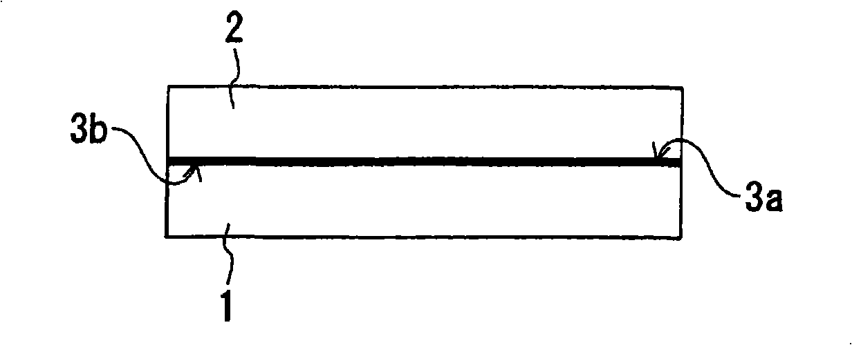
A bonding method by which a resin can be bonded to another resin at a lower temperature than in thermal fusion bonding with satisfactory productivity. The method of resin bonding, which is for bonding a first resin to a second resin, comprises a step (I) in which those surfaces of the first and second resins which are bonding surfaces are irradiated with ultraviolet and a step (II) in which the resins are heated while keeping the irradiated surfaces in contact with each other to thereby bond the first resin to the second resin, with those surfaces used as bonding surfaces. This bonding method can be applied, for example, to a process for producing a resin article comprising two or more parts which each has a resinous area and which have been bonded to each other at the resinous areas, and to a process for producing a microchip comprising a pair of resin substrates bonded to each other face-to-face, at least one of the resin substrates having a fine channel formed therein.

Description

technical field [0001] The present invention relates to a resin bonding method based on light (ultraviolet light) irradiation and a method for manufacturing a resin article such as a microchip using the method. Background technique [0002] As a resin bonding method, there are usually bonding by thermal fusion, or bonding by coating with an organic solvent or an adhesive. Bonding by thermal fusion is usually performed at a temperature equal to or higher than the glass transition temperature of the resin. [0003] On the other hand, a microchip that typically has a structure in which a pair of substrates are bonded facing each other, and in which a fine flow path is formed on the surface of at least one of the substrates is attracting attention. Microchips are also sometimes called microfluidic devices. [0004] In microchips, by providing regions having various functions, such as reaction regions where reagents are placed, in flow paths called microchannels, it is possible...

Claims


Application Information

Patent Timeline
Patent Type & Authority Applications(China)
IPC IPC(8): C09J5/02B32B27/36B29C65/02C08J5/12B29C65/14C09J5/06B32B27/00C12M1/00
CPCB29L2031/756B29C65/48B29C65/1432B29L2031/3425B29K2083/00B29C66/91445B29C66/9241B29C66/91645B29K2995/0039B29K2023/00B29C66/1122B29C66/54B29C66/034B29C66/919B29C65/4845B29C66/026B29C66/0242B29C66/028B29C66/71B29C2035/0827B29C66/91945B29C66/43B29K2995/0026B29C59/16B29K2069/00B29C66/9141B29C66/91411B29C35/02B29C66/53461B29C65/1496B29L2031/3061B29C66/024B29C65/1406B29C66/45B29C66/73117B29C66/73921B29C66/8322B29C66/83221B29K2023/38
Inventor 杉村博之李庚晃谷口义尚田口好弘
Owner ALPS ALPINE CO LTD
Learn More