Method for manufacturing precise metal strip resistor

A manufacturing method and technology of metal strips, applied in the direction of non-adjustable metal resistors, resistors, resistance manufacturing, etc., can solve the problems of inability to flexibly change the shape of the lead-out end, difficulty in adapting to installation needs, low production efficiency, etc., and achieve continuous automation Production, increase the high temperature resistance of welds, and reduce the production process

Inactive Publication Date: 2009-11-25
BDS ELECTRONICS +1
View PDF0 Cites 16 Cited by
  • Summary
  • Abstract
  • Description
  • Claims
  • Application Information

AI Technical Summary

Problems solved by technology

At present, in the production of precision metal strip resistors, lead-tin soldering, silver soldering and other welding methods are used to connect the resistor body material and electrode material. The shortcomings of these welding methods are: manual operation, low production efficiency, impact on the environment, Waste of materials; the processed resistors are large in size, low in precision, high in energy consumption, poor in long-term stability, and poor in thermal stability; they cannot meet the development trend of modern instrument miniaturization and environmental protection, especially it is difficult to meet the surface mount requirements of resistors. process; cannot flexibly change the shape of the lead-out end, and it is difficult to adapt to the installation needs of various application forms

Method used


Image

  • Method for manufacturing precise metal strip resistor
  • Method for manufacturing precise metal strip resistor
  • Method for manufacturing precise metal strip resistor

Examples


Embodiment 1

[0018] This embodiment includes the following steps:

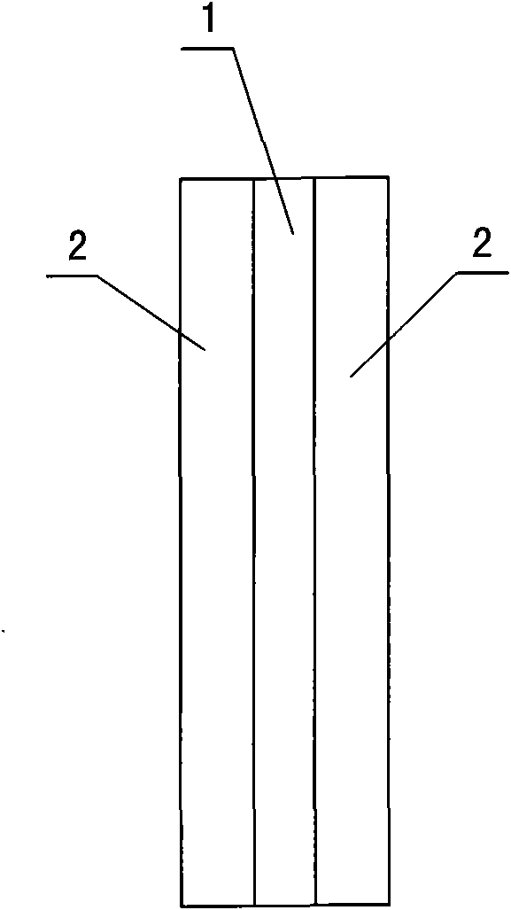
[0019] 1. See figure 1 , take a piece of nickel-chromium alloy strip 1 whose material composition is Cr20%, Cu3%, Al2.8%, Ni balance, thickness is 0.4mm, and width is 5mm. The nickel-chromium alloy strip 1 is a resistor material. Two conductive copper strips 2 with a thickness of 0.4mm and a width of 3.2mm, the conductive copper strips 2 are electrode materials, and the two conductive copper strips 2 are respectively attached to the two sides of the nickel-chromium alloy strip 1, and clamped After clamping and fixing the three parts with the tightening device, clean them;

[0020] 2. Put the three strips fixed together into the welding chamber of the vacuum electron beam welding equipment, and adjust the operating parameters of the electron beam welding equipment to make the vacuum degree 2.2×10 -3 Pa, focus diameter 0.1mm, anode voltage 62KV, welding electron beam power density reaches 10 6 W / cm 2 above, and then weld...

Embodiment 2

[0025] This embodiment includes the following steps:

[0026] see figure 1

[0027] 1. Take a piece of manganese-copper alloy strip 1 whose material composition is Mn20%, Ni3%, and Cu balance, with a thickness of 1mm and a width of 6mm. Take two conductive copper strips 2 with a thickness of 1mm and a width of 20mm. The two conductive copper strips 2 are respectively attached to the two sides of the nickel-chromium alloy strip 1, and the three are clamped and fixed by a clamping device, and then cleaned;

[0028] 2. Put the three strips fixed together into the welding cavity of the vacuum electron beam welding equipment, adjust the operating parameters of the electron beam welding equipment to make the vacuum degree 1.5×10 -3 Pa, focus diameter 0.9mm, anode voltage 70KV, welding electron beam power density reaches 10 6 W / cm 2 above, and then weld the contact parts of the three to form a strip resistor strip;

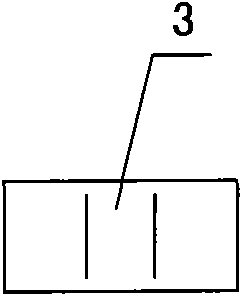
[0029] 3. See Figure 4 , cutting the resistor strip into sev...

Embodiment 3

[0033] This embodiment includes the following steps:

[0034] 1. See Figure 6 , select a manganese-copper alloy sheet 8 with a material composition of Mn13%, Ni3%, and a Cu balance, and a thickness of 0.1mm, and punch out a number of resistors 9 on the alloy sheet 8;

[0035] 2. See Figure 7 , one end of each resistor 9 is disconnected from the alloy sheet 8, and the resistance of each resistor 9 is adjusted. The method adopted is to first use metal cutting means to perform rough adjustment of the resistance value, and then use chemical corrosion to fine-tune the resistance value. tone;

[0036] Then follow the steps below to perform subsequent perfect processing of the resistor body:

[0037] 3. Polish each resistor body 9 and apply a protective agent;

[0038] 4. See Figure 8 , the surface molding plastic layer 10 is carried out on the middle part of the resistor body 9;

[0039] 5. Make a mark on the surface of the plastic layer 10;

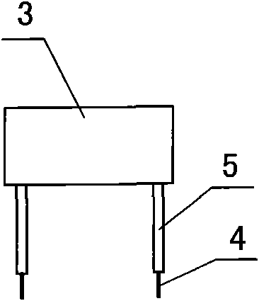
[0040] 6. See Figure 9 , ea...


PUM


Abstract

A method for manufacturing precise metal strip resistor comprises: selecting an alloy strip and two metal strips; cleaning them; welding the two metal strips respectively on two sides of the alloy strip by high energy electron beam welding technique to form an integral resistor strip; punching the resistor strip transversely into a plurality of resistor bodies, or punching the alloy thin plate into a plurality of resistor bodies; then adjusting the numerical resistance values of the resistor bodies; and performing subsequent improvement processing to the resistor bodies to form precise metal strip resistor. Compared with the current technologies, The method provided in the invention reduces more than half of the production processes, increases the efficiency by tem times; reduces the product volume greatly, and realizes the production of surface applied precise splitter with low resistance, small volume and heavy bearable current. The resistor manufactured by the method provided in the invention has the characteristics of good performance, small volume and low material consumption.

Description

technical field [0001] The invention relates to a manufacturing method of a resistor, in particular to a manufacturing method of a precision metal strip resistor. Background technique [0002] Precision metal strip resistors are widely used as current sampling resistors in the fields of intelligent digital watt-hour meters, DC large current measurement, electronic computers, precision instruments, chargers and other electronic equipment. They are widely used current sensors, especially It is suitable for all kinds of electronic instruments produced by surface mount assembly technology. At present, in the production of precision metal strip resistors, lead-tin soldering, silver soldering and other welding methods are used to connect the resistor body material and electrode material. The shortcomings of these welding methods are: manual operation, low production efficiency, impact on the environment, Waste of materials; the processed resistors are large in size, low in precis...

Claims


Application Information

Patent Timeline
Patent Type & Authority Applications(China)
IPC IPC(8): H01C17/24H01C17/245H01C17/26H01C17/28H01C3/00
Inventor 李福喜陆志文
Owner BDS ELECTRONICS
Why Eureka
Try Eureka