Micro Pirani gage

A Raney meter and miniature technology, applied in the direction of microstructure technology, microstructure device, manufacturing microstructure device, etc., can solve the problems of large volume and insufficient sensitivity, and achieve the effect of small volume, high sensitivity and stable performance

Active Publication Date: 2009-12-23
HUAZHONG UNIV OF SCI & TECH
View PDF1 Cites 25 Cited by
  • Summary
  • Abstract
  • Description
  • Claims
  • Application Information

AI Technical Summary

Problems solved by technology

[0005] The invention provides a miniature Pirani meter, which overcomes the problems

Method used


Image

  • Micro Pirani gage
  • Micro Pirani gage
  • Micro Pirani gage

Examples


Embodiment 1

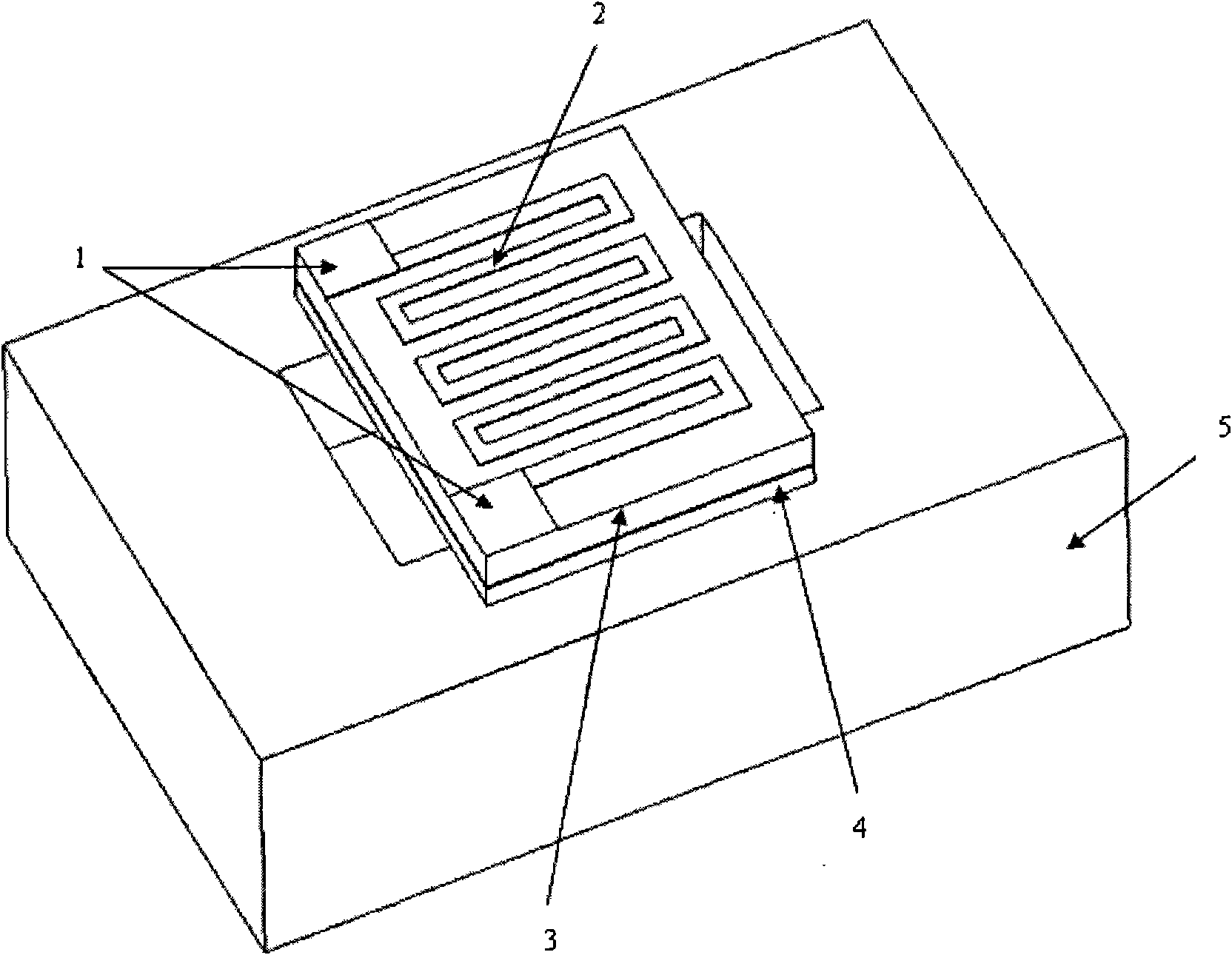
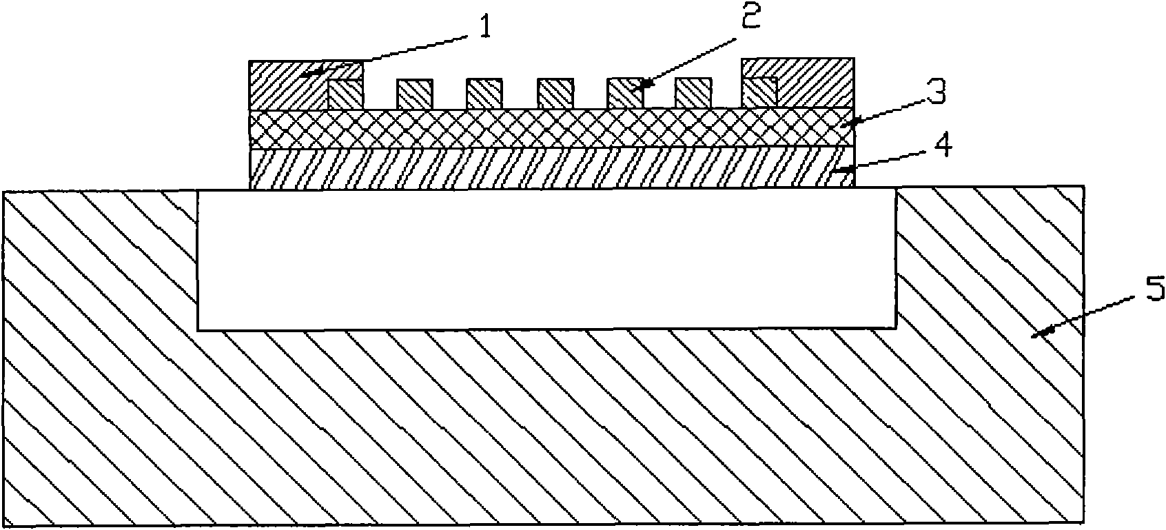
[0034] Embodiment one, such as figure 2 As shown, the silicon substrate 5 is single crystal silicon, and the heating body 2 is platinum metal with a curved shape; the metal electrode 1 is composed of a sputtered Au layer on the surface of the Ti adhesion layer;

[0035] The insulating layer 3 is made of silicon nitride with a thickness of 250nm; the heat insulating layer 4 is made of silicon dioxide with a thickness of 1um.

[0036] The preparation method of this embodiment comprises the following steps in sequence:

[0037] (1) As shown in Figure 3 (A), get a single crystal silicon wafer (2 ", 400um thick, double polishing, (100) orientation) as substrate 5; As shown in Figure 3 (B) on the substrate 5 thermally oxidize the silicon dioxide thin film insulation layer 4 on the surface, and then deposit a low-stress 250nm-thick silicon nitride insulating layer 3 with a low-stress chemical vapor deposition (LPCVD) process; as shown in Figure 3 (C), and then removing the thermal...

Embodiment 2

[0041] Embodiment 2, when the volume of the cavity of the device is large, a part of the back side of the silicon substrate is etched away by a wet method to form a cavity, such as Figure 4 shown. The silicon substrate 5 is single crystal silicon, and the heating body 2 is platinum metal with a curved shape; the metal electrode 1 is composed of a Cu layer sputtered on the surface of the Ti adhesion layer;

[0042] The insulating layer 3 is made of silicon nitride with a thickness of 250nm; the heat insulating layer 4 is made of silicon dioxide with a thickness of 1um.

Embodiment 3

[0043] Embodiment 3, the silicon substrate 5 is polycrystalline silicon, the heating body 2 is nickel metal with a curved shape; the metal electrode 1 is formed by sputtering a Pt layer on the surface of the Ti adhesion layer and then sputtering an Au layer;

[0044] The insulation layer 3 is made of silicon dioxide with a thickness of 250nm; the heat insulation layer 4 is formed by stacking two layers of films, the upper layer is made of silicon nitride with a thickness of 500nm, and the lower layer is made of silicon dioxide with a thickness of 250nm.

[0045] The sandwich structure composed of silicon dioxide-silicon nitride-silicon dioxide can reduce stress.


PUM

PropertyMeasurementUnit
Thicknessaaaaaaaaaa
Thicknessaaaaaaaaaa

Abstract

A micro Pirani gage belongs to vacuum degree measuring element of micro electro mechanical system, aiming at overcoming the problems of large volume and not high enough sensibility of the existing micro Pirani gage. In the invention, a groove is arranged on a silicon substrate, a thermal isolation layer is arranged on the surface of the groove, an insulating layer is covered on the surface of the thermal isolation layer, a heating body is sputtered on the insulating layer, and the two ends of the heating body are sputtered with a metal electrode; wherein the heating body is made by platinum or nickel metal in bend shape; the insulating layer material is silicon nitride or silicon oxide; and the thermal isolation layer material is one or two of silicon oxide and silicon nitride. The invention has small volume, light weight and stable performance, the heating body adopts platinum metal, and the platinum metal has good linearity, stable performance, high sensibility and favourable chemical stability; and the invention has simple manufacturing technology, low cost, high yield and high reliability. The invention is applicable to vacuum degree real time detection in various vacuum encapsulation and micro cavities.

Description

technical field [0001] The invention belongs to a vacuum degree measuring device of a micro-electro-mechanical system (hereinafter referred to as MEMS), and in particular relates to a miniature Pirani gauge. Background technique [0002] Micro-gyroscopes, micro-accelerometers, micro-high-precision tactical oscillators, micro-filters, micro-ultrasonic sensors, microbial molecular mass detectors and other devices based on resonant structures can be packaged in vacuum to reduce the damping of gas during the movement of mechanical moving parts. The quality factor of the device is greatly improved, thereby improving the performance of the device, and the energy consumed by the entire microsystem is also greatly reduced. Devices such as uncooled infrared detectors and imagers, flow meters, and microchromatographs based on the principle of heat conduction need vacuum packaging to prolong the molecular mean free path of free particles and inhibit heat transfer by conduction, thereby...

Claims


Application Information

Patent Timeline
IPC IPC(8): G01L21/12B81B7/02B81C1/00
Inventor 汪学方刘川罗小兵黎藜张卓甘志银张鸿海刘胜
Owner HUAZHONG UNIV OF SCI & TECH
Why Eureka
Try Eureka