
In-situ method for preparing graphene/carbon nanotube composite film

A carbon nanotube composite and in-situ preparation technology, which is applied in the direction of gaseous chemical plating, metal material coating process, coating, etc., can solve the problems that the horizontal composite structure cannot be grown in situ, and the characteristics cannot be fully and effectively exerted. To achieve the effect of thickness controllable

Inactive Publication Date: 2010-04-21
TSINGHUA UNIV
View PDF0 Cites 23 Cited by
  • Summary
  • Abstract
  • Description
  • Claims
  • Application Information

AI Technical Summary

Problems solved by technology

[0003] At present, the research on carbon nanotube / graphene composite structure still has the following deficiencies: 1) only vertical composite structure can be directly synthesized, and horizontal composite structure cannot be grown in situ [reference 3: D.Kondo, S.Sato, Y. Awano.Self-organization of novel carbon composite structure: Graphene multi-layers combined perpendicularly with aligned carbon nanotubes.Appl.Phys.Express.2008, 1(7):074003.]; 2) mostly use liquid phase method, simply mix the two , and assisted by post-reduction processing, the characteristics of the two cannot be fully and effectively used [Reference 4: D.Y.Cai, M.Song, C.X.Xu.Highly conductive carbon-nanotube / graphite-oxide hybrid films.Adv.Mater., 2008 , 20(9): 1706-1709. Reference 5: H.Q.Zhu, Y.M.Zhang, L.Yue, W.S.Li, G.L.Li, D.Shu, H.Y.Chen.Graphite-carbon nanotube composite electrodes for allvanadium redox flow battery.J .Power Sources 2008,184(2):637-640. Reference 6: V.C.Tung, L.M.Chen, M.J.Allen, J.K.Wassei, K.Nelson, R.B.Kaner, Y.Yang.Low-temperature solution processingof graphene-carbon nanotube hybrid materials for high-performance transparent conductors. Nano Lett. 2009, 9(5): 1949-1955.]

Method used


Image

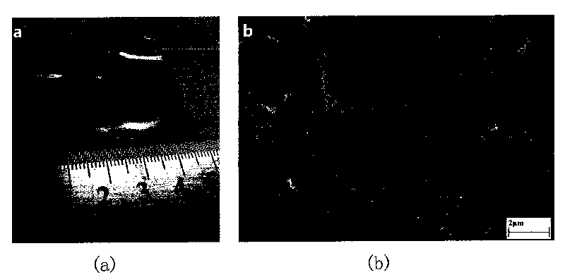
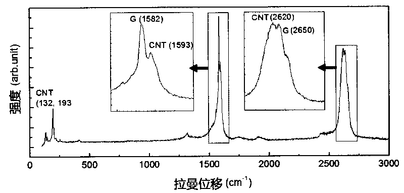
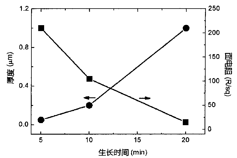
  • In-situ method for preparing graphene/carbon nanotube composite film
  • In-situ method for preparing graphene/carbon nanotube composite film
  • In-situ method for preparing graphene/carbon nanotube composite film

Examples


Embodiment 1

[0019] This embodiment includes the following steps:

[0020] 1. Weigh ferrocene and sulfur with a mass ratio of 58:1, mix them evenly, and place them at the front of the reactor. The purity is 99.5%, the thickness is 0.1mm, and the area is 4×4cm 2 The polycrystalline nickel sheet is placed in the center of the reactor to seal the reactor;

[0021] 2. Inject hydrogen / argon mixed gas with a flow rate of 100 / 200mL / min into the reactor, at the same time raise the temperature of the center of the reactor to 1150°C, and adjust the flow rate of hydrogen / argon to 200 / 1000mL / min;

[0022] 3. Heat the ferrocene and sulfur at the front end of the reactor to 100°C to make them volatilize. The volatile gas is loaded into the reactor from the hydrogen / argon mixed gas adjusted in step 2. Stop heating the ferrocene and sulfur after 10 minutes of reaction. sulfur;

[0023] 4. Stop heating at the center of the reactor, turn off the hydrogen, adjust the flow of argon to 100mL / min, pull out th...

Embodiment 2

[0026] This embodiment includes the following steps:

[0027] 1. Weigh ferrocene and sulfur with a mass ratio of 78:1, mix them evenly, and place them at the front of the reactor. The purity is 99.5%, the thickness is 0.1mm, and the area is 2×2cm 2 cm 2 The polycrystalline nickel sheet is placed in the center of the reactor to seal the reactor;

[0028] 2. Inject hydrogen / argon mixed gas with a flow rate of 150 / 300mL / min into the reactor, and at the same time raise the temperature of the center of the reactor to 1100°C, and adjust the flow rate of hydrogen / argon to 100 / 800mL / min;

[0029] 3. Heat the ferrocene and sulfur at the front end of the reactor to 90°C to volatilize. The volatile gas is loaded into the reactor from the hydrogen / argon gas mixture adjusted in step 2. Stop heating the ferrocene / sulfur after 5 minutes of reaction ;

[0030]4. Stop heating at the center of the reactor, turn off the hydrogen, adjust the flow of argon to 150mL / min, pull out the nickel shee...

Embodiment 3

[0032] This embodiment includes the following steps:

[0033] 1. Weigh ferrocene and sulfur with a mass ratio of 78:1, mix them evenly, and place them at the front of the reactor. The purity is 99.5%, the thickness is 0.1mm, and the area is 2×2cm 2 cm 2 The polycrystalline nickel sheet is placed in the center of the reactor to seal the reactor;

[0034] 2. Inject hydrogen / argon mixed gas with a flow rate of 150 / 300mL / min into the reactor, and at the same time raise the temperature of the center of the reactor to 1100°C, and adjust the flow rate of hydrogen / argon to 100 / 800mL / min;

[0035] 3. Heat the ferrocene and sulfur at the front end of the reactor to 90°C to make them volatilize. The volatile gas is loaded into the reactor from the hydrogen / argon mixture adjusted in step 2, and stop heating the ferrocene / sulfur after 10 minutes of reaction ;

[0036] 4. Stop heating at the center of the reactor, turn off the hydrogen, adjust the flow of argon to 150mL / min, pull out the...


PUM

PropertyMeasurementUnit
thicknessaaaaaaaaaa
thicknessaaaaaaaaaa
purityaaaaaaaaaa

Abstract

The invention relates to an in-situ method for preparing a graphene / carbon nanotube composite film, which comprises the following steps of: 1. weighing ferrocene and sulfur, uniformly mixing and placing the mixture at the front end of a reaction vessel; placing a polycrystal nickel piece in the center of the reaction vessel and sealing the reaction vessel; 2. introducing a hydrogen / argon mixed gas into the reaction vessel, heating the center of the reaction vessel to 1100-1150 DEG C and adjusting the flow of the hydrogen / argon; 3. heating the ferrocene and the sulfur at the front end of the reaction vessel so as to enable the ferrocene and the sulfur to be volatilized and carrying a volatilized gas into the reaction vessel to react by the adjusted hydrogen / argon mixed gas in the step 2; 4. stopping heating the center of the reaction vessel, shutting off the hydrogen, adjusting the flow of the argon, drawing the nickel piece out of the center of the reaction vessel and cooling to room temperature; and obtaining the graphene / carbon nanotube composite film on the nickel piece. The invention realizes the batch production of the graphene / carbon nanotube composite film and has the characteristics of large area, controllable thickness, high electrical conductivity and continuation.

Description

technical field [0001] The invention relates to the field of synthesis and application of nano-carbon materials, in particular to an in-situ preparation method of a graphene / carbon nanotube composite film. Background technique [0002] Carbon nanotubes [reference 1: S.Iijima.Helical microtubules of graphitic carbon.Nature, 1991,354(6348):56-58.] and graphene [reference 2: K.S.Novoselov, A.K.Geim, S.V.Morozov, D. Jiang, Y. Zhang, S. V. Dubonos, I. V. Grigorieva, A. A. Firsov. Electric field effect in atomically thin carbon films. Science, 2004, 306 (5696): 666-669.] are two typical carbon nanomaterials. Graphene is a "single-layer graphite sheet", which is the basic structural unit of graphite; carbon nanotubes are cylindrical structures formed by curling graphene. Both can be used as film materials. However, both carbon nanotubes and graphene have disadvantages as thin film materials alone. The carbon nanotube film has a network structure, and there are large gaps between...

Claims


Application Information

Patent Timeline
Patent Type & Authority Applications(China)
IPC IPC(8): C23C16/26C01B31/02
Inventor 朱宏伟李春艳李虓李昕明韦进全王昆林吴德海
Owner TSINGHUA UNIV
Learn More