
Solution temperature and humidity adjustment air treatment system

An air treatment system, temperature and humidity adjustment technology, applied in air conditioning systems, ventilation systems, shielding with air flow, etc., can solve the problem of high energy consumption, damage to the thermal comfort of air-conditioned rooms, and easy breeding of bacteria and mold, etc. problem, to achieve the effect of large mass transfer driving force

Inactive Publication Date: 2010-05-12
QINGDAO UNIV
View PDF0 Cites 8 Cited by
  • Summary
  • Abstract
  • Description
  • Claims
  • Application Information

AI Technical Summary

Problems solved by technology

[0003] In the existing air treatment system, the four most important processes are cooling, dehumidification, heating and humidification. Among the four processes, the dehumidification process is the most difficult to achieve and consumes the most energy. The traditional air conditioning method Cooling and dehumidification treatment is used to remove the indoor sensible heat load and latent heat load. Although this air-conditioning method can provide a comfortable indoor environment, it has three disadvantages: (1) The traditional air-conditioning method performs combined cooling and dehumidification of the air, making The heat that could have been drained by the high-temperature cold source can be used to share the low-temperature cold source with dehumidification, resulting in a waste of energy utilization grade. This waste is especially prominent in hot and humid areas with large air-conditioning humidity loads; (2) heat and humidify the air In joint treatment, the heat-humidity ratio can only be changed within a certain range, which is difficult to meet the actual needs; when the heat-humidity ratio does not meet the needs, the control of humidity is usually sacrificed, only to meet the required temperature requirements, resulting in air relative humidity If it is too high or too low, it will damage the thermal comfort of the air-conditioned room; (3) The traditional air conditioner uses the cooling surface to cool and dehumidify the air, but the cooling surface is wet or waterlogged, which is easy to breed bacteria and mold, resulting in a decline in the air quality of the air conditioner. Especially after our country experienced "SARS" (atypical pneumonia), the traditional air-conditioning method was questioned by people, and the concept of fresh air air-conditioning began to be valued. The independent miniaturized dehumidification technology has become the research direction of the industry and academia. The liquid temperature and humidity control air treatment system is a green air conditioning method with great development potential in terms of environmental protection and energy saving. At present, experts in the industry are discussing and researching the topic. The efficient heat and mass transfer process realized by the direct contact between the solution and the air can not only realize the dehumidification of the air, but also realize the dehumidification of the air as long as the temperature and concentration of the dehumidification liquid are reasonably controlled and adjusted. cooling, humidification, heating and other processes; but what kind of system can make full use of so many advantages of the high-efficiency heat and mass transfer process when the above-mentioned solution is in direct contact with the air, so as to realize the high-efficiency and energy-saving liquid temperature and humidity control air treatment process .At present, the research work in the field of liquid dehumidification is very active at home and abroad. However, looking at the research situation in recent decades, most of the work is concentrated on the research or experiment of specific components and specific working conditions, such as dehumidification solution The thermophysical properties of the dehumidifier, the dehumidification performance of the dehumidifier, the regeneration capacity of the regenerator, the flow ratio of air and desiccant, etc., and there are many theoretical studies and few experimental verifications. The overall description and overall performance of such systems There are fewer trade-offs, and there has been no major breakthrough in the form of system loops and optimal design.

Method used


Image

  • Solution temperature and humidity adjustment air treatment system
  • Solution temperature and humidity adjustment air treatment system
  • Solution temperature and humidity adjustment air treatment system

Examples


Embodiment 1

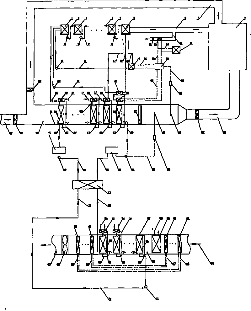
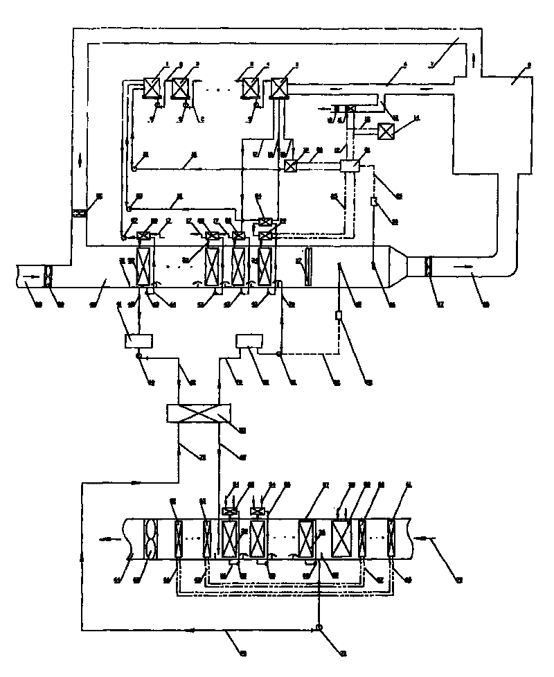
[0037] Fresh air duct 38, fresh air fan 39, return air duct 7, return air fan 22, air treatment section 40, liquid baffle 37, air supply fan 47, air supply duct 48, air user (air-conditioned room) of the present embodiment or drying room) 8, main exhaust air duct 6, branch exhaust air duct 13, and exhaust fan 10 constitute an air circulation subsystem, which makes the air circulate in the air duct and air treatment section through the power provided by various fans. and air users (air-conditioning room or drying room) between reasonable circulation, according to indoor and outdoor temperature and humidity changes, reasonable adjustment of fresh air, return air and exhaust air ratio, to achieve scientific air volume regulation; the working solution tank 31 of this embodiment, working solution Circulation pump 43, working solution supply pipe 44, working solution heat exchanger 28, 29, working solution liquid pipe 33, solution processing liquid device (internal structure is packe...

Embodiment 2

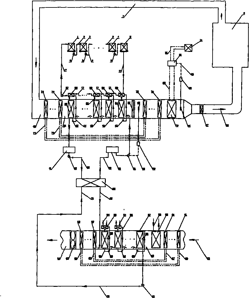
[0040] The return air duct 7 of the present embodiment, the air treatment section 40, the liquid baffle plate 37, the blower fan 47, the air supply duct 48, the air user (air-conditioning room or drying room) 8 etc. constitute the air circulation subsystem, and the subsystem The power provided by the blower fan makes the air circulate reasonably between the air duct, the air treatment section and the air user (air-conditioned room or drying room); the working solution tank 31 of this embodiment, the working solution circulating pump 43, the working solution Liquid supply pipe 44, working solution heat exchanger 28, working solution liquid distribution pipe 33, solution processing liquid separation device (internal structure can be packed bed type, can be packed tower type, can be spray chamber type, also can be spray Shower tube type; the packing in the packed tower type can be structured packing or bulk packing) 32, 34, etc. constitute an N-level solution processing subsystem ...


PUM


Abstract

The invention belongs to the technical field of energy source engineering and relates to a solution temperature and humidity adjustment air treatment system, which is a high-efficiency and energy-saving system that combines a heat and mass transfer system and heat pipe energy conservation and heat pump energy conservation technology to realize the temperature and humidity adjustment air treatment. The system is an integrated solution temperature and humidity adjustment air treatment system formed by organically communicating an air circulation subsystem, an N-stage solution treatment subsystem, a solution flowing and storing subsystem, an M-stage solution regeneration subsystem, a P-stage heat pipe heat return subsystem, a heat pump cold or heat supply subsystem, an L(or L+1)-stage air cooling tower subsystem, a cooling water circular flow subsystem, a temperature control subsystem and a humidity control subsystem with a low-temperature auxiliary heat source, wherein N is more than or equal to 1 and less than or equal to 20; and N is equal to M, P and L. The system has the advantages of mineral and energy conservation, slight pollution, novel and simple structure, combined temperature and humidity control process, small dehumidification module volume, large mass transfer driving force, high energy utilization rate, energy conservation, high heat pump efficiency, wide application range and the like.

Description

Technical field: [0001] The invention belongs to the technical field of energy engineering, and relates to a solution temperature and humidity control air treatment system. The high-efficiency heat and mass transfer process realized by the direct contact between the solution and the air is organically combined with the heat pipe energy-saving technology and the heat pump energy-saving technology to realize air conditioning. High-efficiency energy-saving system for temperature and humidity control. Background technique: [0002] Air treatment systems are widely used in fields such as industry, agriculture, commerce and people's family life. For example: in the convection drying process widely used in industrial and agricultural production, the air treatment system is its drying power source, and the annual energy consumption of the air treatment system used for drying power source is quite huge; All kinds of air conditioners used in family life are also air treatment systems,...

Claims


Application Information

Patent Timeline
Patent Type & Authority Applications(China)
IPC IPC(8): F24F3/044F24F12/00
Inventor 田小亮魏彦丹孙晖王兆俊刘瑞景
Owner QINGDAO UNIV
Learn More