Manufacturing method of permanent magnetic gear

A manufacturing method and gear technology, applied in the manufacture of inductors/transformers/magnets, electrical components, pipes/pipe joints/pipe fittings, etc., can solve the problem of reduced reliability and it is difficult to apply to areas where the cleaning line is completely exposed to moisture. Low satisfaction and other issues, to achieve the effect of improving satisfaction

Inactive Publication Date: 2010-07-14
威海利奥泰儆自动化设备有限公司
View PDF7 Cites 1 Cited by
  • Summary
  • Abstract
  • Description
  • Claims
  • Application Information

AI Technical Summary

Problems solved by technology

However, when the surface magnetic velocity density is as low as about 1550G, most soft magnetic materials have the disadvantage of being easily oxidized, so subsequent coating is required, and the economic effect will be low and the reliability will also decrease.
Therefore, it is difficult to apply to areas such as cleaning lines that are completely exposed to moisture, or areas where acid-base chemicals are used, etc.
From this point of view, the previously applicable permanent magnet gear manufacturing method has certain limitations in use conditions, and there is always a problem of low satisfaction in terms of implementation methods or multiple application ranges.

Method used


Image

  • Manufacturing method of permanent magnetic gear
  • Manufacturing method of permanent magnetic gear
  • Manufacturing method of permanent magnetic gear

Examples


Embodiment 1

[0021] According to the previous technology, its magnetism is 37HR grade (residual magnetic velocity density = 12.6kG, coercive force = 17kOe, maximum energy product = 37Moe) rare earth radial ring sintered magnet and JHNC157 grade (residual magnetic velocity density = 7kG, coercive force = 8kOe, maximum energy product = 9.5Moe) Each pair of rare earth equilateral bond magnets is coated with electrophoretic epoxy resin and coated on the surface, and then manufactured into a size of 39mmΦ x 32mmΦ x 26mm high. After assembling this with a non-magnetic POM Holder with an outer diameter of 32mmΦ x an inner diameter of 17mmΦ x a height of 30mm, it is magnetized with 10 poles and 45 degrees skew poles for use as permanent magnet gears. While rotating in the direction of the outer diameter of the magnet, the surface layer magnetic velocity density was measured with a Gauss meter and the results are shown in Table 1. The maximum surface magnetic velocity densities of the aforementione...

Embodiment 2

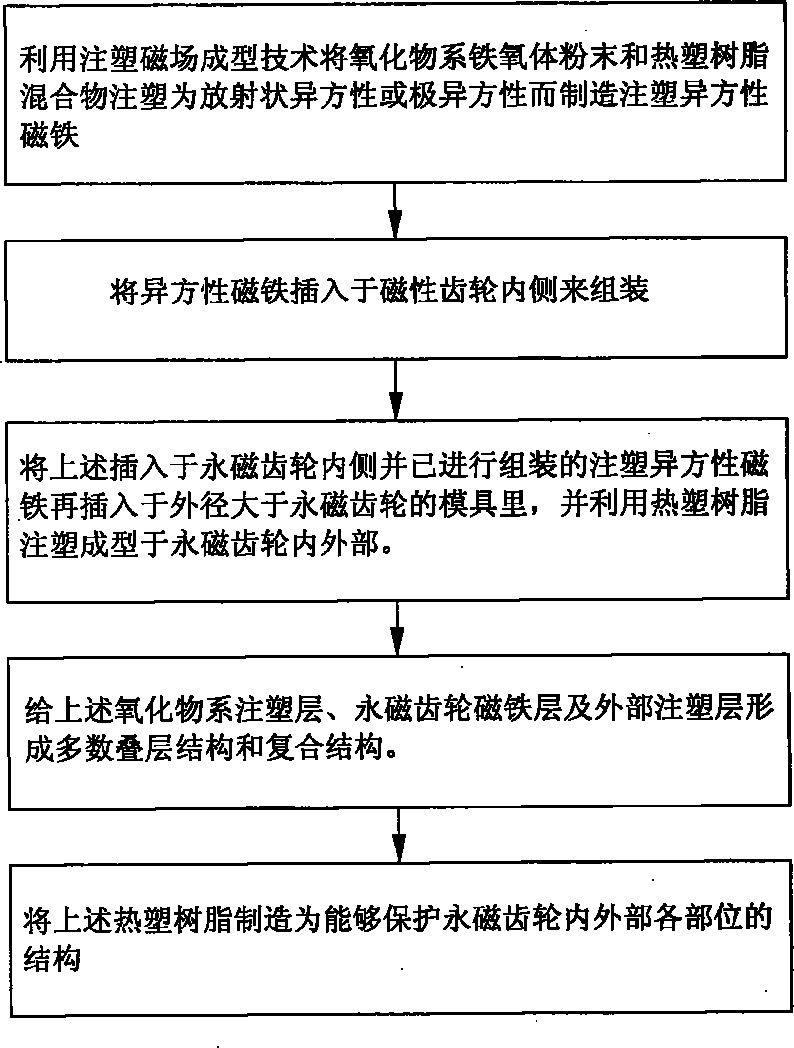
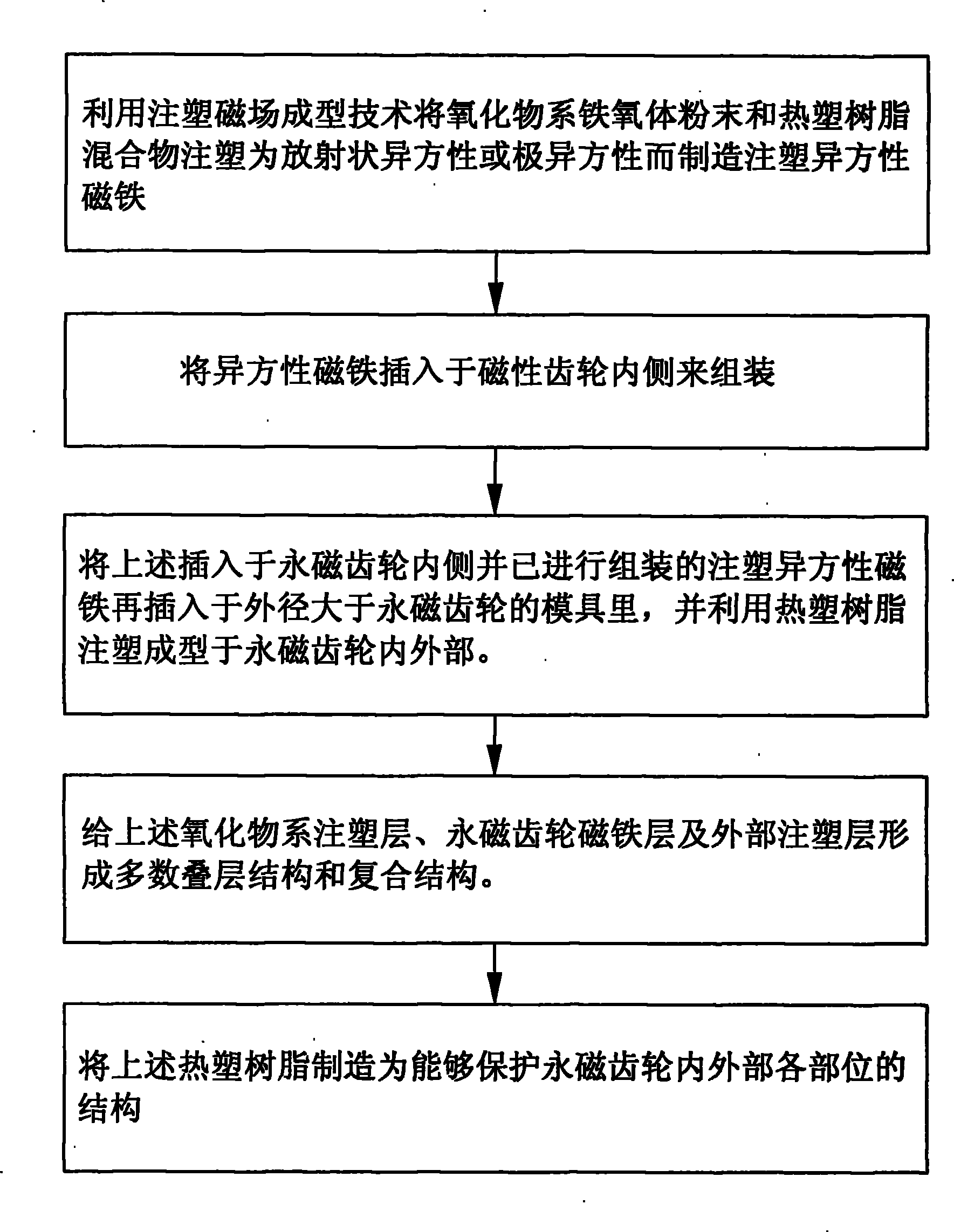
[0025] Sr-Ferrite powder (OP-71 manufactured by Nippon Bengara) and amine coupling agent A-1120 (manufactured by Unikar, Japan) were diluted with nucleic acid, etc., mixed uniformly with an attritor and dried to perform powder surface treatment. Add thermoplastic resin Nylon12 (ZZ3000P manufactured by Degussa) and fatty acid amide (manufactured by Huaxing Japan) that can improve fluidity to this powder, and use a 2-axis mixing air compressor to make small pellets at 210-260 ° C. Then, put the ball into the magnetic field injection mold, and under the injection molding conditions of mold temperature 80°C, injection temperature 220-270°C, and injection pressure 900-1500kg / cm2, the size of outer diameter 32mmΦ×inner diameter 17mmΦ×height 26mmt is produced. The 10-pole anisotropic resin magnet. Among the above-mentioned projects, the project of injection molding with extremely anisotropic magnetic field for each mixture is the most important project to implement isotropicization o...

Embodiment 3

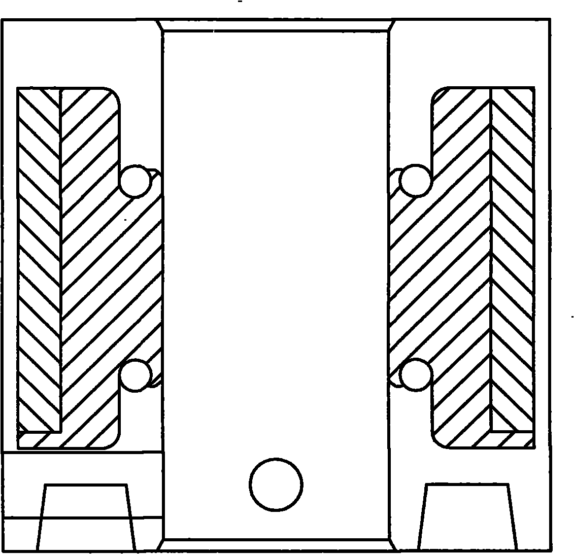
[0029]Using the same small pellets and magnetic field injection molding conditions as in Example 2 above, the first magnetic field injection molding was performed on a 10-pole 45-degree skew magnetization pole anisotropy mold with an outer diameter of 32mmΦ and an inner diameter of 17mmΦ to manufacture an outer diameter of 32mmΦ×inner diameter of 17mmΦ×height 26mmt ferrite pole anisotropic magnet. On this magnet, the outer diameter 39mmΦ×inner diameter 32mmΦ×high 26mm size 37HR rare earth Radial ring permanent magnet and JHNC157grade (residual magnetic velocity density (Br)=7kG, coercive force (Hc)=8kOe, Maximum magnetic energy product (Bhmax) = 9.5MOe) After each pair of rare earth isotropic Bond magnets, in order to maximize the surface magnetic velocity density of the permanent magnet gear, the magnets are assembled in the direction of mutual attraction. Put this again into an injection mold with an outer diameter of 40mmΦ×inner diameter of 17mmΦ×a height of 32mm, and perfo...


PUM


Abstract

The invention relates to a manufacturing method of a permanent magnetic gear, which comprises the following steps: (1) manufacturing an injection molding anisotropic magnet; (2) assembling the anisotropic magnetic gear; (3) putting the injection molding anisotropic magnet of the step (2), which is inserted into the inside of the permanent magnetic gear and is assembled, into a mold the external diameter of which is larger than that of the permanent magnetic gear, and machining the interior and the exterior of the permanent magnetic gear by using thermoplastic resin in an injection molding way; (4) an oxide series injection molding layer, a permanent magnetic gear magnet layer and an external injection layer which are produced in the step (2) into a multi-laminated structure and a composite structure; and (5) manufacturing the thermoplastic resin of the step (3) into a structure which can protect each part of the interior and the exterior of the permanent magnetic gear. The invention has the beneficial effects: since the oxide series injection molding layer, the permanent magnetic gear magnet layer and the external injection layer form the multi-laminated structure and the composite structure, the magnetism of the anisotropic injection molding magnet can be improved, rotary torque can be increased, and simultaneously, the oxidative resistance of the interior of the permanent magnetic gear can be improved.

Description

technical field [0001] The invention relates to a manufacturing method of a permanent magnet gear. Background technique [0002] Generally speaking, permanent magnet gears are used in semiconductor and LCD manufacturing and inspection load equipment that require a clean environment due to their advantages of no contact and no dust generation. According to the trend of increasing the size of the carrier, in order to increase the load Ability to use high-performance rare-earth magnets. When the rare earth magnet is used as a permanent magnet gear, it has the advantage of high magnetism and the disadvantage of being easily corroded due to oxidation. In order to make up for this, surface coating is necessary, but it has a problem of low economic benefit due to its engineering complexity and low yield. And depending on the use environment, it also shows unstable reliability, that is, there will be some restrictions on use in an atmospheric environment with low humidity. Someti...

Claims


Application Information

Patent Timeline
Patent Type & Authority Applications(China)
IPC IPC(8): B29C45/14B29C45/16H01F41/02F16L55/17
Inventor 丁太虎
Owner 威海利奥泰儆自动化设备有限公司
Why Eureka
Try Eureka