Wet flue gas desulphurizing method utilizing carbide slag slurry and device thereof

A wet flue gas desulfurization and calcium carbide slag slurry technology is applied in the field of flue gas purification, which can solve the problems of flexible configuration of desulfurization slurry concentration and lack of complete consideration of the process, so as to ensure long-term stable operation, meet the desulfurization standard requirements, and reduce costs. Effect

Inactive Publication Date: 2010-08-11
INST OF PROCESS ENG CHINESE ACAD OF SCI
View PDF2 Cites 29 Cited by
  • Summary
  • Abstract
  • Description
  • Claims
  • Application Information

AI Technical Summary

Problems solved by technology

The above two patents cannot flexibly configure the desulfurization slurry concentration according t

Method used


Image

  • Wet flue gas desulphurizing method utilizing carbide slag slurry and device thereof
  • Wet flue gas desulphurizing method utilizing carbide slag slurry and device thereof
  • Wet flue gas desulphurizing method utilizing carbide slag slurry and device thereof

Examples


preparation example Construction

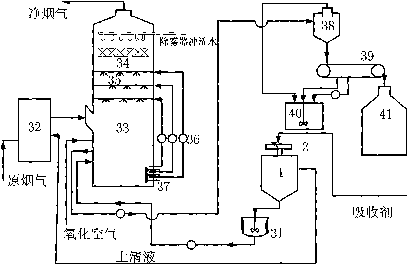
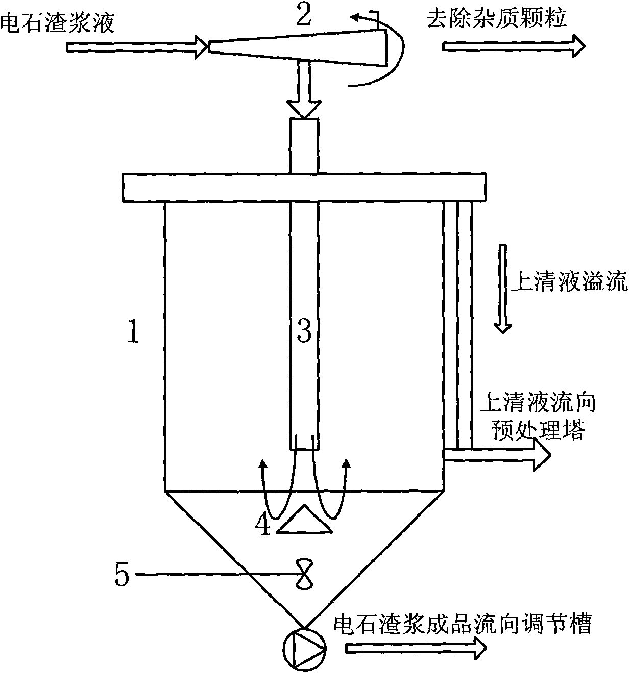
[0052] The function of the desulfurizer system is the preparation of the desulfurizer, which is mainly composed of a thickening device 1, a calcium carbide slurry regulating tank 31, an agitator, a pump and other equipment. The desulfurization agent is made of calcium carbide slurry in the chemical plant area, which is filtered to remove slag, concentrated, and then enters the regulating tank. At the same time, it is stirred to prevent precipitation, and the resulting slurry is transported to the absorption tower by a slurry pump.

[0053] (2) Desulfurization tower system

[0054] The flue gas from the dust collector first enters the pretreatment tower 32, and then enters the absorption tower 33. In the tower, the flue gas exchanges heat, mass transfers, and reacts with the desulfurization slurry atomized by spraying. The mist eliminator 34 removes most of the entrained liquid, which is discharged from the top of the absorption tower.

[0055] The absorption tower 33 is cylin...

Embodiment 1

[0063] A 3×90t / h boiler flue gas desulfurization device in a chemical plant adopts the technology of the present invention, and the flue gas volume at the inlet of the desulfurization device is 365610Nm 3 / h, inlet sulfur dioxide concentration 11000mg / m 3 , the concentration of sulfur dioxide at the outlet of the desulfurization unit is 380mg / m3 3 , when the Ca / S molar ratio of the system is 1.05-1.1, the desulfurization efficiency is >96%. Desulfurization gypsum moisture content ≤ 10%, CaSO in desulfurization gypsum 4 Content ≥ 87%. The diameter of the absorption tower is 5.8m, the height is 29m, the pressure drop of the absorption tower is 1200Pa, and the slurry circulation residence time is 6 minutes.

Embodiment 2

[0065] A 130+75t / h boiler flue gas desulfurization device in a chemical plant adopts the technology of the present invention, and the flue gas volume at the inlet of the desulfurization device is 313000Nm 3 / h, inlet sulfur dioxide concentration 12000mg / m 3 , the concentration of sulfur dioxide at the outlet of the desulfurization unit is 400mg / m 3 , when the Ca / S molar ratio of the system is 1.05-1.1, the desulfurization efficiency is >96%. Desulfurization gypsum moisture content ≤ 12%, CaSO in desulfurization gypsum 4 Content ≥ 86%. The diameter of the absorption tower is 5m, the height is 25m, the pressure drop of the absorption tower is 1000Pa, and the slurry circulation residence time is 5.5 minutes.

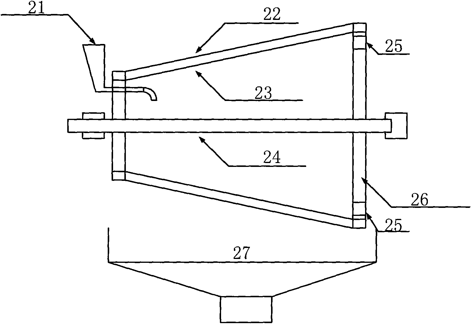
[0066] Such as image 3 As shown, the low-speed rotary filter 2 of the present invention includes: a slurry inlet 21 on the front end face, an outer screen 22, an inner screen 23, a rotating shaft 24, an outlet 25 and a water retaining plate 26, in this example , the o...


PUM

PropertyMeasurementUnit
Diameteraaaaaaaaaa

Abstract

The invention discloses a wet flue gas desulphurizing method utilizing carbide slag slurry and a device thereof. The method comprises the following steps: 1) firstly, concentrating carbide slag slurry into carbide slag seriflux the concentration of which is 20-30%; 2) adjusting the concentration of sulphur content in flue gas, controlling the concentration of the carbide slag seriflux within the range of 28%-35% when the sulphur content in flue gas is larger than 8000mg/m3, controlling the concentration of the carbide slag seriflux is within the range of 22%-28% when the sulphur content in flue gas is between 4000mg/m3 and 8000mg/m3, controlling the concentration of the carbide slag seriflux within the range of 15%-22% when the sulphur content in flue gas is smaller than 4000mg/m3, regulating to proper concentration and then entering an absorption tower to carry out desulfuration reaction; 3) carrying out preliminary desulfuration reaction on flue gas which comes out from a deduster and firstly enters a pretreater; and 4) carrying out reaction on flue gas and sprayed and atomized carbide slag slurry in an absorption tower to realize rapid heat exchange, mass transfer and reaction, removing most of the entertainment liquid in the flue gas after reaction by a demister and discharging the flue gas from the top of the absorption tower. The invention can be applied to flue gas desulfurization of coal-fired boilers of a chemical plant, thereby achieving the purposes of treating waste by waste and utilizing comprehensively.

Description

technical field [0001] The invention relates to the field of flue gas purification, in particular to a method and device for wet flue gas desulfurization, which utilizes calcium carbide slag slurry discharged from a chemical plant as a desulfurization absorbent after concentration treatment. Background technique [0002] Carbide slurry is the waste of polyvinyl chloride resin (PVC) produced by calcium carbide method. Carbide hydrolysis to obtain acetylene gas produces calcium hydroxide slag slurry with a solid content of 3% to 12%. Chemical companies that produce polyvinyl chloride have a large amount of calcium carbide slag, which is produced after treatment. Long-term open-air stacking of calcium carbide slag not only occupies valuable land resources, but also pollutes soil and shallow groundwater, making soil salinization. Therefore, how to realize the utilization of calcium carbide slurry is the focus of enterprises. [0003] Carbide slag slurry is slightly soluble in ...

Claims


Application Information

Patent Timeline
IPC IPC(8): B01D53/50B01D53/80
Inventor 朱廷钰荆鹏飞叶猛
Owner INST OF PROCESS ENG CHINESE ACAD OF SCI
Why Eureka
Try Eureka