External circulation enclosed photocatalytic reduction CO2 reaction device

A technology of reaction device and external circulation, applied in chemical instruments and methods, chemical/physical processes, chemical/physical/physicochemical processes of energy application, etc. In order to achieve the effect of improving photocatalytic efficiency, good gas-liquid circulation rate and convenient product detection

Inactive Publication Date: 2010-10-27
NORTHWEST UNIV(CN)
View PDF7 Cites 11 Cited by
  • Summary
  • Abstract
  • Description
  • Claims
  • Application Information

AI Technical Summary

Problems solved by technology

[0003] However, the current photocatalytic reduction of CO 2 Also there are following problems: 1, TiO2 widely used at present 2 Photocatalysts can only absorb ultraviolet light (λ2 The photoresponse range has become a current research hotspot; 2. Photocatalytic reduction of CO 2 There are various types of reactors, according to TiO 2 The forms of existence in the reaction system are mainly fixed and suspended, such as film and fluidized bed photocatalytic reactors
Although the fixed type can solve the problem of photocatalyst recovery, the specific surface area of ​​the reaction is greatly reduced, and the utilization rate of light is not high; compared with the fixed type, the suspension type photoreactor can improve the photocatalytic efficiency, but the light Catalyst recovery is difficult and the recovery cost is high; 3. TiO 2 Combining modification and reaction device development to improve overall photocatalytic reduction of CO 2 There are few studies on the efficiency of the reaction system, which needs to be further developed
[0004] At present, many photocatalytic reaction devices have been reported, such as: the new gas photocatalytic reactor disclosed in the Chinese patent application (patent number: ZL200520047134.5), the photocatalytic reaction for treating waste water and waste gas disclosed in the Chinese patent application (patent number ZL01248388.0) device and a Chinese patent application (application number: 200610113267.7) disclosed a device for continuous sewage treatment using a magnetic photocatalyst, but these reaction devices are not suitable for photocatalytic reduction of CO 2 reaction, although there is also photocatalytic reduction of CO 2 For example, the Chinese patent application (Application No.: 200710062304.8) discloses a three-phase ultrasonic photocatalytic reaction device and its reduction of CO 2 method, but it belongs to the suspension reaction system, and there are still problems of photocatalyst recovery difficulty and high recovery cost

Method used


Image

  • External circulation enclosed photocatalytic reduction CO2 reaction device
  • External circulation enclosed photocatalytic reduction CO2 reaction device
  • External circulation enclosed photocatalytic reduction CO2 reaction device

Examples


Embodiment 1

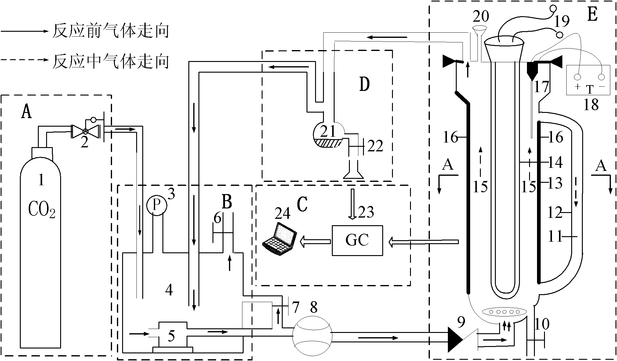
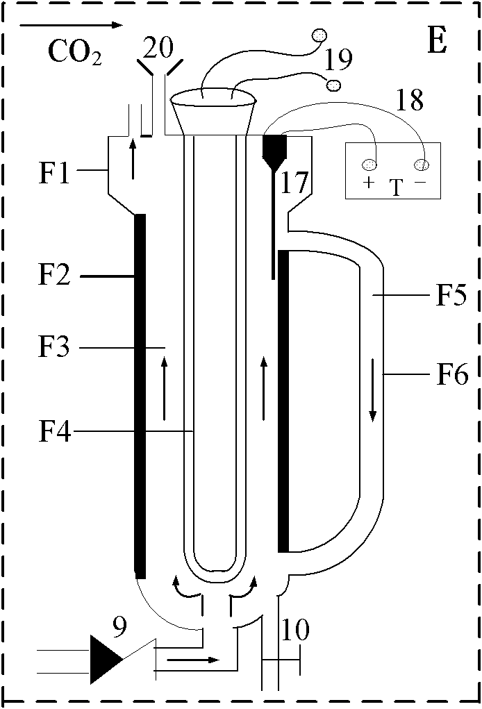
[0030] Embodiment 1: Reaction system composition: the Na of preparation 0.10mol / L 2 SO 3 and 600 mL of 0.10 mol / L NaOH solution, put an appropriate amount of catalyst into the solution, and sonicate for 5 minutes. Then add the above-mentioned reaction solution into the outer circulation closed type photocatalytic reduction CO of the present invention 2 Reactor. CO 2 Pass it into the bottom of the reactor at a certain flow rate, turn on the ultraviolet lamp after 30 minutes, and turn off the gas source. Methanol content was analyzed by gas chromatography. Gas chromatography conditions: carrier gas N 2 60mL / min, H 2 The flow rate is 50mL / min, the air flow rate is 50mL / min, the column temperature is 90°C, the injection port is 150°C, and the detector is 180°C. Na added in the system 2 SO 3 It can provide electrons, absorb the holes generated by the illuminated semiconductor, and inhibit the recombination of electron-hole pairs, and adding NaOH can make the reaction syste...

Embodiment 2

[0031] Embodiment 2: Improved sol-gel method prepares Fe 3+ doped TiO 2 Powder photocatalyst and reduction of CO 2 Performance test: At room temperature, put butyl titanate, n-butanol, and glacial acetic acid in a molar ratio of 1:4:4 into an Erlenmeyer flask, stir for 0.5 hours, add ferric nitrate, and react for 8 hours. Obtain a light yellow transparent solution, place it for aging for 24 hours, dry it at 75°C, and then calcinate and grind it at 500°C to obtain granular Fe 3+ doped TiO 2 Catalyst, denoted as Fe-TiO 2 . Weigh 0.6g Fe-TiO 2 Mix with the reaction solution of Example 1 and add the outer circulation airtight photocatalytic reduction CO of the present invention 2 Reaction in the reaction device for 8h, CH 3 The OH yield was 60.13 μmol / g-cat (amount of methanol produced per gram of catalyst).

Embodiment 3

[0032] Embodiment 3: hydrothermal method prepares pure TiO 2 Nanotube Photocatalyst and CO Reduction 2 Performance test: put butyl titanate, n-butanol, and glacial acetic acid in a conical flask at a molar ratio of 1:4:4, and react for 8 hours to obtain a light yellow transparent solution, age for 24 hours, and dry at 75°C Calcined and ground at 500°C to obtain granular pure TiO 2 powder catalyst. Take the above TiO 2 Put 2g of the powder into 100mL10moL / L NaOH solution, ultrasonically oscillate for 5 minutes, put it into an autoclave, and react at a temperature of 110°C with a hydrothermal reaction time of 12h, 24h, and 36h. After the reaction, the solid-liquid mixture After centrifugation, the separated solid was calcined in a muffle furnace at 400°C for 2 hours to obtain three TiO 2 The nanotube samples are respectively denoted as TNTs-12, TNTs-24, and TNTs-36. Weigh 0.6g of the above-mentioned nanotube catalyst and mix it with the reaction solution of Example 1 and ad...


PUM


Abstract

The invention relates to an external circulation enclosed photocatalytic reduction CO2 reaction device, which comprises a gas supply system, a circulation system, a detection system, a separation system and a reaction system. A light source is arranged in the center of a reactor; a photocatalyst is suspended in reaction liquid; CO2 gas serving as stirring power enters the reaction system from the bottom of the reactor to drive the reaction liquid and the catalyst to circulate in the reactor; on the separation section on the top of the reactor, partial gas is brought into an external circulation downcomer by the reaction liquid, and partial gas leaves the reactor and enters the reactor again through the circulation system; reaction products are brought out by the gas and separated in a condenser; and the separation system and the detection system can respectively collect and analyze the reaction products at any time. The reactor is suitable for a photocatalytic reduction CO2 reaction system and other gas-liquid-solid three-phase photocatalytic reaction.

Description

technical field [0001] The invention belongs to a photocatalytic reaction device in the technical field of resources and environment, and relates to a photocatalytic reaction device with an outer circulation closed type. Background technique [0002] Environmental pollution and energy shortage have become the most important problems facing the development of the world today. With the rapid development of the global economy and the increasing consumption of fossil energy, a large amount of CO 2 Emissions have become one of the main causes of environmental pollution and climate warming. will CO 2 Transforming into energy substances can not only save fossil resources such as coal, oil and natural gas, but also turn harm into treasure, which has obvious economic and environmental benefits. Therefore CO 2 The transformation and utilization of has become a hot spot for scientists. In numerous processes CO 2 In the method, the reduction of CO in aqueous solution is combined wi...

Claims


Application Information

Patent Timeline
Patent Type & Authority Applications(China)
IPC IPC(8): B01J19/12B01J8/08B01D53/86B01D53/62
CPCY02A50/20
Inventor 樊君温凯刘恩周胡晓云何奇杨宇豪代宏哲胡蕊
Owner NORTHWEST UNIV(CN)
Why Eureka
Try Eureka