Laser machining device

A technology of laser processing and laser beam, which is applied in the direction of fine working devices, auxiliary devices, metal processing, etc., can solve problems such as the complexity of laser optical systems, and achieve the effect of reducing the driving mechanism, small driving force, and reducing the installation space

Inactive Publication Date: 2010-11-03
MITSUBOSHI DIAMOND IND CO LTD
View PDF4 Cites 6 Cited by
  • Summary
  • Abstract
  • Description
  • Claims
  • Application Information

AI Technical Summary

Problems solved by technology

[0038] However, in the case of using an elliptical beam spot to process a glass substrate, semiconductor wafer, etc. (assuming that the processing directions of the substrate are the X direction and the Y direction) into a square shape, it is necessary to change the orientation of the long axis direction of the beam spot from the X direction of the substrate. The direction is changed to

Method used


Image

  • Laser machining device
  • Laser machining device
  • Laser machining device

Examples


no. 1 approach

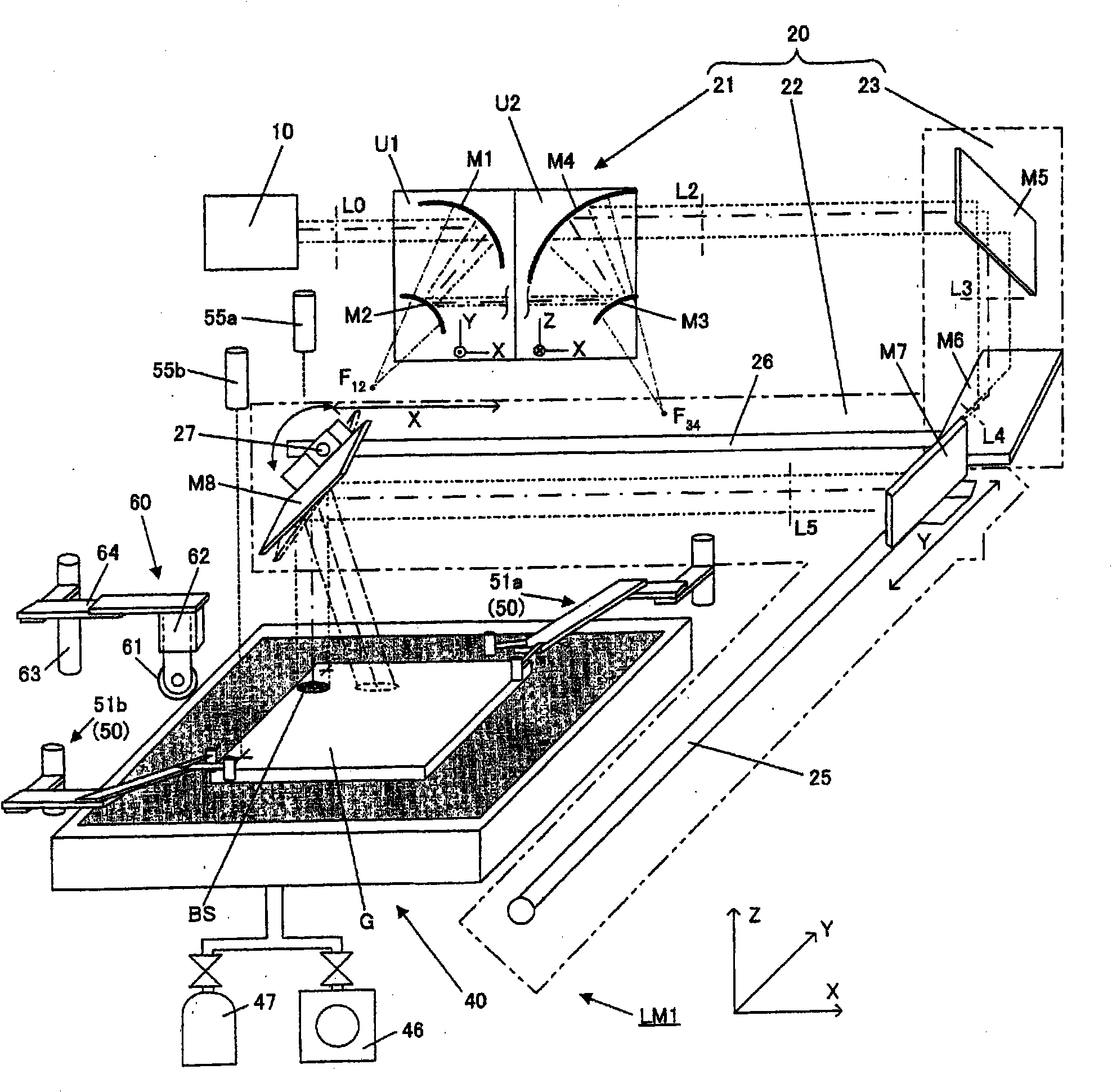
[0118] figure 1 It is the whole structure diagram of the laser processing apparatus LM1 which is one Embodiment of this invention. The laser processing device LM1 is mainly composed of a laser light source 10 , a laser scanning optical system 20 , a table 40 , a substrate guide mechanism 50 , and a trigger mechanism 60 .

[0119] (laser light source)

[0120] The laser light source 10 adopts CO 2 laser. Can also replace CO 2 Lasers use CO lasers and excimer lasers. A laser beam (original beam L0 ) having a circular cross-sectional shape is emitted from the laser light source 10 . In addition, in the case of laser ablation processing, a laser light source having a wavelength and an energy density capable of melting and evaporating the substrate material is used.

[0121] (laser scanning optical system)

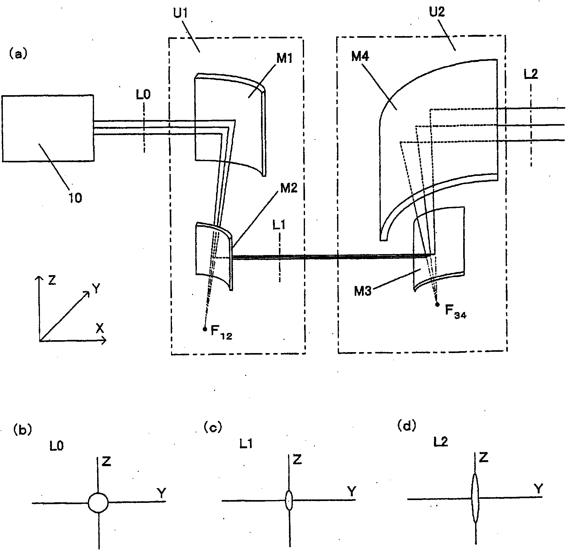
[0122] The laser scanning optical system 20 is roughly composed of the following parts: a beam shaping part 21 that adjusts the cross-sectional shape of the laser beam;...

no. 2 approach

[0170] Next, a second embodiment of the present invention will be described. Figure 7 It is an overall configuration diagram of a laser processing apparatus LM2 as a second embodiment of the present invention, Figure 8 It is a block diagram which shows the control system of laser processing apparatus LM2. For and use Figure 1 to Figure 6The parts common to the structure of the description are assigned the same symbols, and the description of this part is omitted. The laser processing device LM2 is modified from the laser processing device LM1 in that a variable focus parabolic mirror is movably attached, and a control unit 80a is configured by adding a parabolic mirror drive unit 88 for driving the parabolic mirror.

[0171] Figure 9 It is a figure which shows the structural example of the beam shaper 21a of the laser processing apparatus LM2.

[0172] The beam shaper 21 a is composed of four optical elements of a first parabolic mirror (concave surface) M1 , a second ...


PUM


Abstract

A laser machining device enabling a reduction in installation space and rotation of a substrate by using a fixed table without using a table rotating mechanism. A laser machining device comprises a positionally fixed table (40) whose substrate mounting surface is formed by a porous member and which is provided with a suction mechanism for holding a substrate by suction via the porous member and alevitation mechanism for levitating the substrate by spraying gas thereto via the porous member, a laser source (10), a laser beam scanning optical system (20) for shaping a laser beam emitted from the laser source into a laser beam with an elliptical cross-section and leading the shaped laser beam to a machining surface of the substrate to scan the machining surface, and a substrate guiding mechanism (50) for, when the substrate mounted on the table is positioned or moved, guiding the substrate by a movable abutting portion which moves the substrate by pushing a substrate side surface in thedirection horizontal to the table surface while abutting on the substrate side surface of the levitated substrate. The laser machining device moves and rotates the substrate to a desired position by pushing the substrate side surface by the substrate guiding mechanism while levitating the substrate.

Description

technical field [0001] The invention relates to a laser processing device for processing a substrate to be processed by scanning a laser beam. [0002] Laser processing in the present invention includes laser scribing processing of brittle materials such as glass substrates, sintered ceramics, single crystal silicon, semiconductor wafers, ceramic substrates, etc., using thermal stress generated when laser heating is performed at a temperature below the softening point, And laser ablation processing that heats materials other than brittle materials at a temperature above the melting temperature. Background technique [0003] A scanning laser processing apparatus that performs processing by relatively moving an irradiation position of a laser beam with respect to a substrate to be processed has been used for processing a brittle material substrate such as a glass substrate. [0004] In this laser processing device, in order to achieve the purpose of reducing the processing wi...

Claims


Application Information

Patent Timeline
IPC IPC(8): B23K26/02B23K26/073B23K26/10B23K26/14B28D7/04B23K26/364B28D5/00
CPCB23K26/0807B23K37/0408B23K26/073B23K26/082B23K26/032B23K26/0853B23K2101/36
Inventor 森田英毅在间则文
Owner MITSUBOSHI DIAMOND IND CO LTD
Why Eureka
Try Eureka