Normal temperature bonding technology-based microminiature fuel cell encapsulation method

A packaging method and fuel cell technology, which can be applied in fuel cells, fuel cell components, and microstructure technology, etc., can solve problems such as increasing the difficulty of packaging operations, affecting cell performance and reliability, and polluting fuel cell membrane electrodes.

Active Publication Date: 2010-11-24
TSINGHUA UNIV
View PDF2 Cites 8 Cited by
  • Summary
  • Abstract
  • Description
  • Claims
  • Application Information

AI Technical Summary

Problems solved by technology

However, the current packaging of micro fuel cells is mainly achieved by clamping or gluing, and these methods have certain limitations.
The battery packaging method using clamps greatly increases the battery volume and reduces the overall energy density of the battery device, which deviates from the original intention of fuel cell miniaturization (such as fuel cells involved in some recent literature: Small direct methanol fuel cells with passive supply of reactants, T.S.Zhao et al, Journal of Power Sources 191(2009)185-202; Influence of current collectors design on the performance of a silicon-based passive micro direct methanol fuel cell, J.P.Esquivel et al, Journal of Power Sources 194(2009) 391-396); and the membrane electrode of the fuel cell may be polluted by gluing, which affects the performance and reliability of the battery (a packaging method for micro fuel cells, Zhang Xigui, etc., Chinese Academy of Sciences Shanghai Institute of Microsystem and Information Technology, public number CN101079492, public date 2007-11-28)
In addition, the method of packaging batteries with jigs will increase the number of components in the entire battery device, and the packaging process will introduce additional positioning links. The positioning of battery components needs to be completed or assisted by jigs, which not only increases the difficulty of packaging operations, but also High-precision positioning fixtures will greatly increase the cost of battery packaging

Method used


Image

  • Normal temperature bonding technology-based microminiature fuel cell encapsulation method
  • Normal temperature bonding technology-based microminiature fuel cell encapsulation method
  • Normal temperature bonding technology-based microminiature fuel cell encapsulation method

Examples


Embodiment 1

[0068] The present invention will be further described below in conjunction with accompanying drawing:

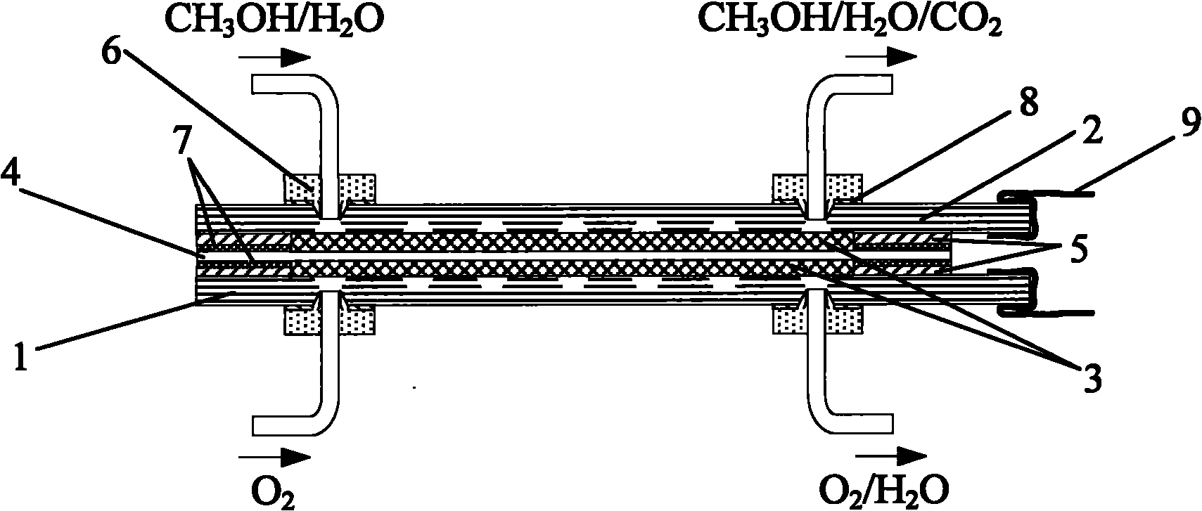
[0069] Such as figure 1 Shown is a schematic diagram of the structure of a micro fuel cell packaged without a clamp. The micro fuel cell has a sandwich structure inside, including a cathode plate 1, an anode plate 2, a flow field sealing gasket 5 and a membrane between the two plates The electrode, the cathode plate and the anode plate are the front side near the membrane electrode, and the back side is the back side. The front side includes micro channels for fuel transmission and a patterned metal layer for drawing current. The membrane electrode is made of carbon paper 3 consists of anode carbon paper, cathode carbon paper and proton exchange membrane 4. A cathode catalyst is loaded on the cathode side of the proton exchange membrane, and an anode catalyst is loaded on the anode side.

[0070] The micro fuel cell described above is packaged by a packaging method based ...

Embodiment 2

[0118] The present invention will be further described below in conjunction with accompanying drawing:

[0119] Such as figure 1 Shown is a schematic diagram of the structure of a micro fuel cell packaged without a clamp. The micro fuel cell has a sandwich structure inside, including a cathode plate 1, an anode plate 2, a flow field sealing gasket 5 and a membrane between the two plates The electrode, the cathode plate and the anode plate are the front side near the membrane electrode, and the back side is the back side. The front side includes micro channels for fuel transmission and a patterned metal layer for drawing current. The membrane electrode is made of carbon paper 3 consists of anode carbon paper, cathode carbon paper and proton exchange membrane 4. A cathode catalyst is loaded on the cathode side of the proton exchange membrane, and an anode catalyst is loaded on the anode side.

[0120] The micro fuel cell described above is packaged by a packaging method based ...


PUM

PropertyMeasurementUnit
thicknessaaaaaaaaaa
thicknessaaaaaaaaaa
thicknessaaaaaaaaaa

Abstract

The invention discloses a normal temperature bonding technology-based microminiature fuel cell encapsulation method, which belongs to the technical field of processing and systems of microfluids and micromachining. A polar plate surface after being processed by oxygen plasma is bonded to a flow field sealing washer of a micro-proton exchange membrane fuel cell (PEMFC) so as to realize ordered assembly of a cell component by bonding or using a solid adhesive tape. A boding interface between a silicon polar plate and the flow field sealing washer and an adhesive on the solid adhesive tape provide a pressure required for fastening the cell component. A layer of diaphragm seal is deposited on the surface of the cell body of the micro-PEMFC to realize complete sealing of the micro-PEMFC and achieve an effect on protecting the cell body. The method reduces moveable components in the cell body, reduces difficulties in encapsulation, avoids performance reduction of a proton exchange membrane because of the damage which is caused by high-temperature dehydration, avoids the pollution to MEA and other cell components, does not need to use a positioning clamp for clamping, does not increase cell device volume, and simultaneously ensures the reliability of a cell.

Description

technical field [0001] The invention belongs to the field of microfluidics and micromachining and system technology, and in particular relates to a micro-miniature fuel cell packaging method based on room temperature bonding technology. Background technique [0002] In recent years, various micro-devices based on MEMS (Micro-Electro-Mechanical Systems, Micro-Electro-Mechanical Systems) technology have developed rapidly and have been widely used, but the development of corresponding micro-energy devices is relatively slow. The energy devices of common micro devices are larger in size, several times larger than working devices, which seriously weakens the advantages of micro devices and micro systems in terms of miniaturization and high integration. In recent years, with the rapid development of portable devices such as mobile phones and notebook computers, micro fuel cells with small volume and high energy density are being widely studied. However, the current encapsulation ...

Claims


Application Information

Patent Timeline
Patent Type & Authority Applications(China)
IPC IPC(8): H01M8/02B81C1/00H01M8/0276
CPCY02E60/50Y02P70/50
Inventor 王晓红朱一鸣周彦安刘理天
Owner TSINGHUA UNIV
Why Eureka
Try Eureka