
Method for realizing slowly-varying lamination antireflection coating of solar cell

A solar cell, anti-reflection technology, applied in coatings, circuits, electrical components, etc., can solve the problems of long time and difficult control.

Inactive Publication Date: 2011-01-26
TRINASOLAR CO LTD
View PDF3 Cites 13 Cited by
  • Summary
  • Abstract
  • Description
  • Claims
  • Application Information

AI Technical Summary

Problems solved by technology

Takes a long time and is not easy to control

Method used


Image

  • Method for realizing slowly-varying lamination antireflection coating of solar cell
  • Method for realizing slowly-varying lamination antireflection coating of solar cell

Examples


Embodiment Construction

[0014] The present invention will now be described in further detail.

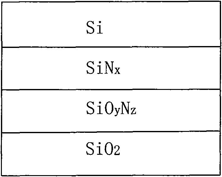
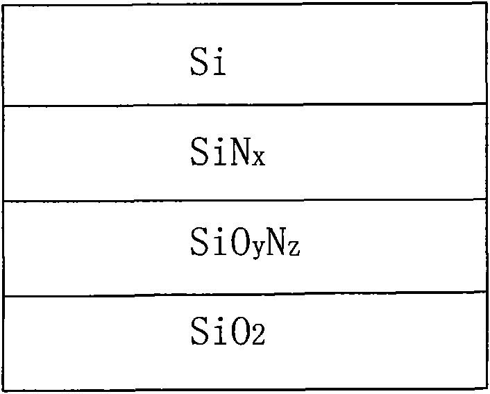
[0015] The method for realizing the solar cell slow-change stacked anti-reflection film is to deposit the anti-reflection film on the light-receiving surface of the solar cell silicon wafer after treatment through the chemical vapor deposition process, and the gas at the beginning of the deposition is SiH 4 and NH 3 mixed gas or SiH 4 and N 2 mixed gas, N was gradually added during the deposition process 2 O, so that the composition of the film changes from silicon nitride on the surface of the silicon wafer to silicon oxynitride on the outer layer and then to silicon dioxide on the outer layer.

[0016] The chemical vapor deposition process is to deposit on the front side of the silicon wafer at a temperature of 200°-400°. The silicon wafer is P-type or N-type single crystal silicon, and the resistivity of the silicon wafer is 0.2Ωcm-10Ωcm. The gas at the beginning of the chemical vapor deposition pr...


PUM


Abstract

The invention relates to the field of solar cell production methods, in particular to a method for realizing a slowly-varying lamination antireflection coating of a solar cell. In the method, a radiation surface of a treated solar cell silicon wafer is subject to deposition antireflection coating by a chemical vapor-phase deposition process, gases at beginning of deposition are mixed gas of SiH4 and NH3 or mixed gas of SiH4 and N2; and N2O is gradually added in a depositing process to ensure that components of the coating is varied from silicon nitride on the surface of the silicon wafer, to nitric oxide of silicon of an outer layer, and to the silicon dioxide to the outset layer, wherein the thickness of the coating is between 50 and 300nm. The method has high deposition speed and high yield and can realize deposition of various coatings at once; and the deposited coating has high compactness, can effectively reduce the interface state caused by different coating combination, and has the unique advantage of the silicon oxynitride and the advantages of silicon oxide and silicon nitride. The method has the advantages of simple and easy control, low cost and high efficiency.

Description

technical field [0001] The invention relates to the field of solar cell production methods, in particular to a method for realizing a solar cell slow-change laminated anti-reflection film. Background technique [0002] Photovoltaic power generation is a very important field in the utilization of solar energy. It is an urgent task to seek new technologies, new materials, and new processes to improve battery conversion efficiency and reduce costs. [0003] The conversion efficiency is directly related to the light intensity entering the PN junction region of the silicon wafer. More incident light intensity can generate more effective electron-hole pairs and improve the photoelectric conversion efficiency. Reducing the reflectivity of the surface of the silicon wafer is an effective means to increase the light entering the interior of the silicon wafer. The existing methods for reducing the reflectivity are: 1. Texture the surface. At present, almost all solar cells are texture...

Claims


Application Information

Patent Timeline
IPC IPC(8): H01L31/18C23C16/52
CPCY02P70/50
Inventor 刘亚锋
Owner TRINASOLAR CO LTD
Learn More