
Special equipment for laser micro-cladding

A technology of laser micro cladding and special equipment, applied in laser welding equipment, welding equipment, metal processing equipment, etc., can solve the problem of difficult to meet industrial rapid composite manufacturing, inability to combine micro-pen micro-spray and laser, and inability to preset different materials and other problems, to achieve the effect of shortening processing time, high degree of automation, and shortening diffusion time

Active Publication Date: 2011-04-13
HUAZHONG UNIV OF SCI & TECH
View PDF4 Cites 14 Cited by
  • Summary
  • Abstract
  • Description
  • Claims
  • Application Information

AI Technical Summary

Problems solved by technology

However, there are several problems in using the rotary coating method to preset the film layer: first, the thickness of the preset film is not uniform; second, the excess slurry needs to be removed after laser direct writing, and the cleaned slurry cannot be recycled. Material waste is serious; third, this method cannot preset different materials on the same substrate
However, the existing working platform cannot meet the requirements of the composite process, and the distribution of tools is scattered. When multiple materials are preset on the same substrate, the direct writing device needs to be replaced and cleaned frequently, and the relative position and adjustment of the processing tool and the substrate must be relocated. Therefore, in actual processing, there are many repetitive tasks and complicated operation steps, and it is impossible to maximize the advantages of micro-pen, micro-spray and laser composite, and it is difficult to meet the requirements of industrial rapid composite manufacturing. It is only suitable for laboratories. research work or small batch production

Method used


Image

  • Special equipment for laser micro-cladding
  • Special equipment for laser micro-cladding
  • Special equipment for laser micro-cladding

Examples


Embodiment Construction

[0025] The laser used in the present invention may be a semiconductor laser, a solid laser, a fiber laser or a lamp-pumped solid laser. The above-mentioned lasers can adopt continuous or quasi-continuous output mode.

[0026] The invention is suitable for direct writing of electronic pastes of various materials and different properties, and can quickly obtain electronic components with good performance. The electronic paste includes conductive paste, resistance paste, dielectric paste or other electronic paste, and the substrate can be ceramic, glass, silicon, epoxy resin, polyimide and other materials.

[0027] The present invention will be further described below in conjunction with the accompanying drawings.

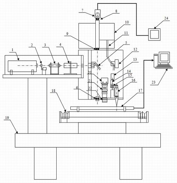
[0028] The equipment of the invention mainly includes five parts: a workbench, a laser processing system, a CCD monitoring and positioning system, a direct writing system and a control system.

[0029] like figure 1 As shown, the workbench includes an operation tab...


PUM


Abstract

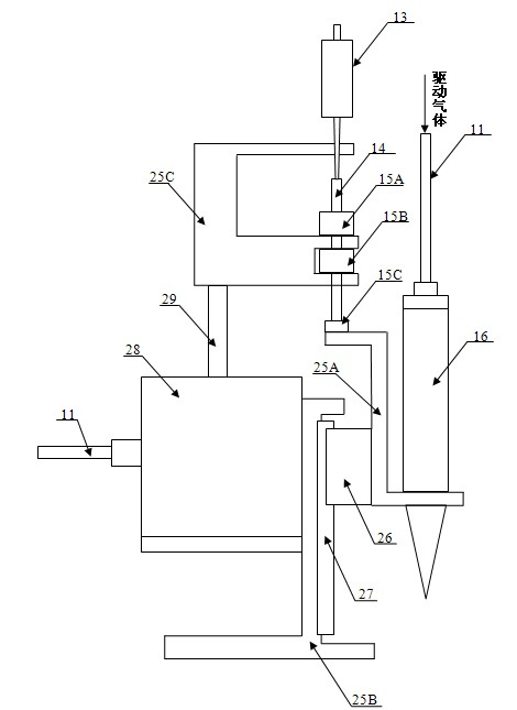
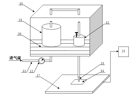
The invention discloses special equipment for laser mirco-cladding. The equipment comprises a workbench, a laser processing system and a control system, and is characterized by also comprising a charge coupled device (CCD) monitoring and positioning system and a direct writing system, wherein the CCD monitoring and positioning system comprises a coaxial CCD sensor, a paraxial CCD sensor, a zoom lens, an imaging eye lens, a zoom optical system, a paraxial imaging object lens and an external monitor; the direct writing system comprises a micro-pen direct writing device and a micro-jet direct writing device; the micro-pen direct writing device comprises a support, a guide rail, a cylinder, a slider, a piston rod, a dial gauge, a micro adjustment nut and a micropen; and the micro-jet direct writing device comprises a water bath kettle, a gas-guide tube, a micro-pressure gauge and a micro-jet tool. In respect of the equipment, a laser optical path and the installation stations and working modes of the micro-jet direct writing device and the micropen are reasonably designed, and laser processing, the micropen and the micro-jet direct writing system are integrated on the same working platform, thereby realizing advantage complementation of various processing methods.

Description

technical field [0001] The invention belongs to the technical field of electronic / optoelectronic manufacturing, and specifically relates to a special equipment for laser micro cladding. Fabrication of waveguides. Background technique [0002] The emergence and development of large-scale integrated circuits has led to the continuous development of electronic manufacturing technology in the direction of integration, miniaturization, short timeliness, small batches, multi-variety and three-dimensional manufacturing. Layer wiring, the factor that restricts the further improvement of the quality of electronic products has changed from the original chip size to the interconnection line spacing between chips. [0003] In 2000, the inventor proposed the technology of laser micro cladding electronic paste to prepare wires, that is, laser micro cladding flexible direct writing technology, and developed the manufacturing system and equipment based on this technology. This technology ...

Claims


Application Information

Patent Timeline
IPC IPC(8): C23C24/10B23K26/02B23K26/14B23K26/34
Inventor 蔡志祥曾晓雁段军张洁李祥友王泽敏
Owner HUAZHONG UNIV OF SCI & TECH
Learn More