Biofeedback photoelectric therapeutic device

A biofeedback and therapeutic device technology, applied in the field of medical devices, can solve problems affecting the survival of electrode nerve cells, increasing the distance between electrodes and target neurons, and limited time and space resolution of transcranial direct electrical stimulation.

Active Publication Date: 2011-04-20
SHENZHEN INST OF ADVANCED TECH CHINESE ACAD OF SCI
View PDF2 Cites 25 Cited by
  • Summary
  • Abstract
  • Description
  • Claims
  • Application Information

AI Technical Summary

Problems solved by technology

At the same time, due to the diffusion effect, the temporal and spatial resolution of transcranial direct electrical stimulation are very limited.
Although deep brain stimulation has a certain therapeutic effect, there are still many shortcomings: First, deep brain stimulation lacks selectivity and specificity, and in many cases the mechanism of treatment is not clear, therefore, in the process of stimulation There is a certain degree of unpredictability, and may even have side effects
Secondly, after long-term implantation of stimulation devices, inflammatory reactions are often caused due to surgical trauma and biocompatibility of implanted materials. With the formation of astrocyte cysts, the impedance of the electrode interface will increase significantly. Large, the stimulating effect is significantly weakened
In addition, cysts will also affect the survival of nerve cells around the electrode, increasing the distance between the electrode and the target neuron, which will seriously affect the therapeutic effect of deep brain stimulation
In addition, deep brain electrical stimulation is difficult to achieve neuron inhibition

Method used


Image

  • Biofeedback photoelectric therapeutic device
  • Biofeedback photoelectric therapeutic device
  • Biofeedback photoelectric therapeutic device

Examples


Embodiment 1

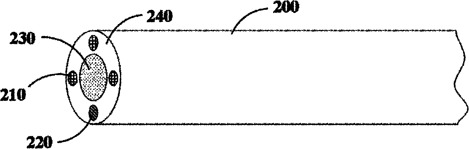
[0053] Such as image 3 As shown, the photoelectrode 200 of this embodiment includes 3 working electrodes and 1 reference electrode. The electrode core 210 of the working electrode (hereinafter referred to as the working electrode core 210 ) and the electrode core 220 of the reference electrode (hereinafter referred to as the reference electrode core 220 ) are metal microwires. The working electrode core 210 and the reference electrode core 220 are distributed around the surface of the optical fiber 230 , and the distance between the electrode cores (including the working electrode core 210 and the reference electrode core 220 ) and the optical fiber 230 is 0-1 mm. The insulating layer 240 wraps the working electrode core 210 , the reference electrode core 220 and the optical fiber 230 to form a columnar photoelectrode 200 .

[0054] In this embodiment, the material of the working electrode core 210 is iridium oxide, and the material of the reference electrode core 220 is sil...

Embodiment 2

[0056] Such as Figure 4 As shown, the photoelectrode 300 of this embodiment includes an optical fiber 310 and an annular electrode core 320 distributed around the surface of the optical fiber 310 . The ring width of the ring electrode core 320 is less than 200 μm. The ring electrode core 320 is a metal micropipe or a metal, metal compound, carbon material or conductive polymer deposited around the optical fiber 310 . Among them, the deposition process can be realized by chemical deposition, chemical vapor deposition, ion sputtering, magnetron sputtering or high temperature evaporation. The outer layer of the ring-shaped electrode core 320 is encapsulated by an insulating layer 330, and one end of the ring-shaped electrode core 320 is exposed to form a ring-shaped electrode. The ring-shaped electrode core 320 is in direct contact with the optical fiber 310, so that EEG recording or photoelectric stimulation therapy can be performed more accurately. In addition, the ring ele...

Embodiment 3

[0059] Such as Image 6 As shown, the size of the photoelectrode 400 in this embodiment is smaller, and its structure is roughly the same as that of the photoelectrode 300 in the second embodiment. The photoelectrode 400 is located inside the catheter 500 , and the photoelectrode 400 is connected to the catheter 500 through a connecting device 510 at one end. Similar to Embodiment 2, the catheter 500 of this embodiment can also be used as a reference electrode. Since the photoelectrode 400 is small, it can be used as a monopolar photoelectrode implanted in a deep part, which can reduce surgical trauma and enhance the selectivity of the electrode.


PUM


Abstract

The invention relates to a biofeedback photoelectric therapeutic device comprising an information collection system, a control system and a biofeedback therapeutic system, wherein the information collection system is used for collecting physiologic information of a human cranial part in real time and transferring the physiologic information to the control system for analysis treatment; and the control system is used for controlling the biofeedback therapeutic system according to an analysis treatment result of the physiologic information to carry out the photoelectric stimulation therapy of corresponding nervous system diseases. The biofeedback photoelectric therapeutic device is used for measuring biological, chemical or physical signals of related tissues, particularly focal tissues through the information collection system, and the biofeedback therapeutic system is used for adopting corresponding therapeutic measures according to detected signal data. The invention has specificity, selectivity, stronger purposive property and safer and effective therapy.

Description

【Technical field】 [0001] The invention relates to the field of medical equipment, in particular to a biofeedback photoelectric therapy device. 【Background technique】 [0002] With the continuous acceleration of the pace of life, people generally face various social, environmental and work pressures, and their bodies and minds are often in a state of high fatigue and tension. Many factors that endanger mental health increase accordingly, making depression, epilepsy and other nervous system diseases obvious. increase. In addition, as the global population gradually ages, neurodegenerative diseases are increasing and becoming a major social burden. [0003] The incidence of neurological diseases is gradually increasing, which not only brings infinite pain to patients, but also creates a huge burden on society. Traditionally, a combination of drugs and surgery has been used in the treatment of neurological diseases. However, long-term use of drugs has relatively large side ef...

Claims


Application Information

Patent Timeline
Patent Type & Authority Applications(China)
IPC IPC(8): A61N5/06A61N1/36A61N1/04A61M35/00
Inventor 鲁艺王立平
Owner SHENZHEN INST OF ADVANCED TECH CHINESE ACAD OF SCI
Why Eureka
Try Eureka