
Parallel connection protection circuit for solar module

A protection circuit and module technology, which is applied in emergency protection circuit devices, emergency protection circuit devices for limiting overcurrent/overvoltage, circuits, etc., can solve the problem of reducing the effective voltage output of solar cells and shortening the time for effective power generation during the day , Improve the cost of solar photovoltaic power generation and other issues, to achieve the effect of promoting promotion, simple structure, and increasing output power

Inactive Publication Date: 2011-07-20
SUZHOU DONGLING VIBRATION TEST INSTR
View PDF3 Cites 8 Cited by
  • Summary
  • Abstract
  • Description
  • Claims
  • Application Information

AI Technical Summary

Problems solved by technology

However, because the forward voltage drop of the diode is 0.7V, the output voltage and efficiency are reduced, and because the effective voltage output of the solar cell is reduced, the effective power generation time during the day is shortened, and the actual output power of the solar energy is greatly reduced.
According to the calculation of 12V solar cells, the annual power generation will lose about 11%, which increases the cost of solar photovoltaic power generation, thus limiting the promotion of new energy

Method used


Image

  • Parallel connection protection circuit for solar module
  • Parallel connection protection circuit for solar module
  • Parallel connection protection circuit for solar module

Examples


Embodiment 1

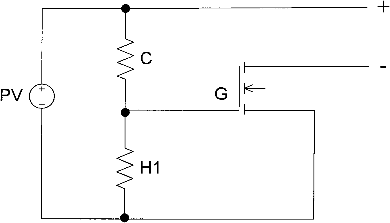
[0029] Embodiment 1. Two resistors are used to form a control module:

[0030] Such as Figure 3a The structure of the control module shown includes a resistor C connected in series as a drive module and a resistor H1 as a protection module, and the value relationship between the two resistors satisfies R H1 :R C =U G :(U PV -U G ), where U G is the gate driving voltage of the FET, U PV is the output voltage of the solar module. Such as gate drive voltage U G 2V, PV output voltage U PV is 12V, it can be calculated that R H1 :R C The resistance value ratio is 1:5. The larger the resistance value, the smaller the current passing through the resistor, and the smaller the loss generated, but the resistance value should not be too large, which will lead to unstable control, and the gate of the field effect transistor should be guaranteed drive current. The principle of this example is simple, the cost is the lowest, and the reliability is high in the applicable voltage ...

Embodiment 2

[0032] Embodiment 2: A resistor is used, and a plurality of diodes are connected in series to form a control module:

[0033] Such as Figure 3b As shown, in this example, the drive module still uses a resistor C, while the protection module uses several diodes in series to form a diode string H2, each of which contains a diode voltage drop of 0.7V, and the number of diodes matches the field effect The multiple of the gate driving voltage of the transistor relative to the voltage drop of a single diode, that is, the example can control the gate driving voltage of the field effect transistor through the number of diodes, and make it basically stable at a fixed voltage value.

[0034] This example uses the stable junction voltage of the diode to basically stabilize the gate drive voltage, which can adapt to different PVs and has strong versatility.

Embodiment 3

[0035]Embodiment 3, using a resistor and a control module composed of a Zener diode:

[0036] Such as Figure 3c As shown, in this example, the drive module uses a resistor C, and the protection module uses a Zener diode H3. The voltage regulation value of the Zener diode is determined according to the drive voltage value of the gate of the field effect transistor, and usually exceeds the gate voltage of the field effect transistor. The driving voltage of the pole is enough to make it work in a fully turned-on state, but it cannot exceed the breakdown voltage of the gate. The Zener diode stabilizes the voltage value through the leakage current. There are no high requirements for the selection of the drive circuit, that is, the resistance C, and it only needs to meet the drive current requirements of the field effect tube area. The circuit of this example is simple, stable and reliable, has strong versatility, and can be suitable for various application requirements.

[0037]...


PUM


Abstract

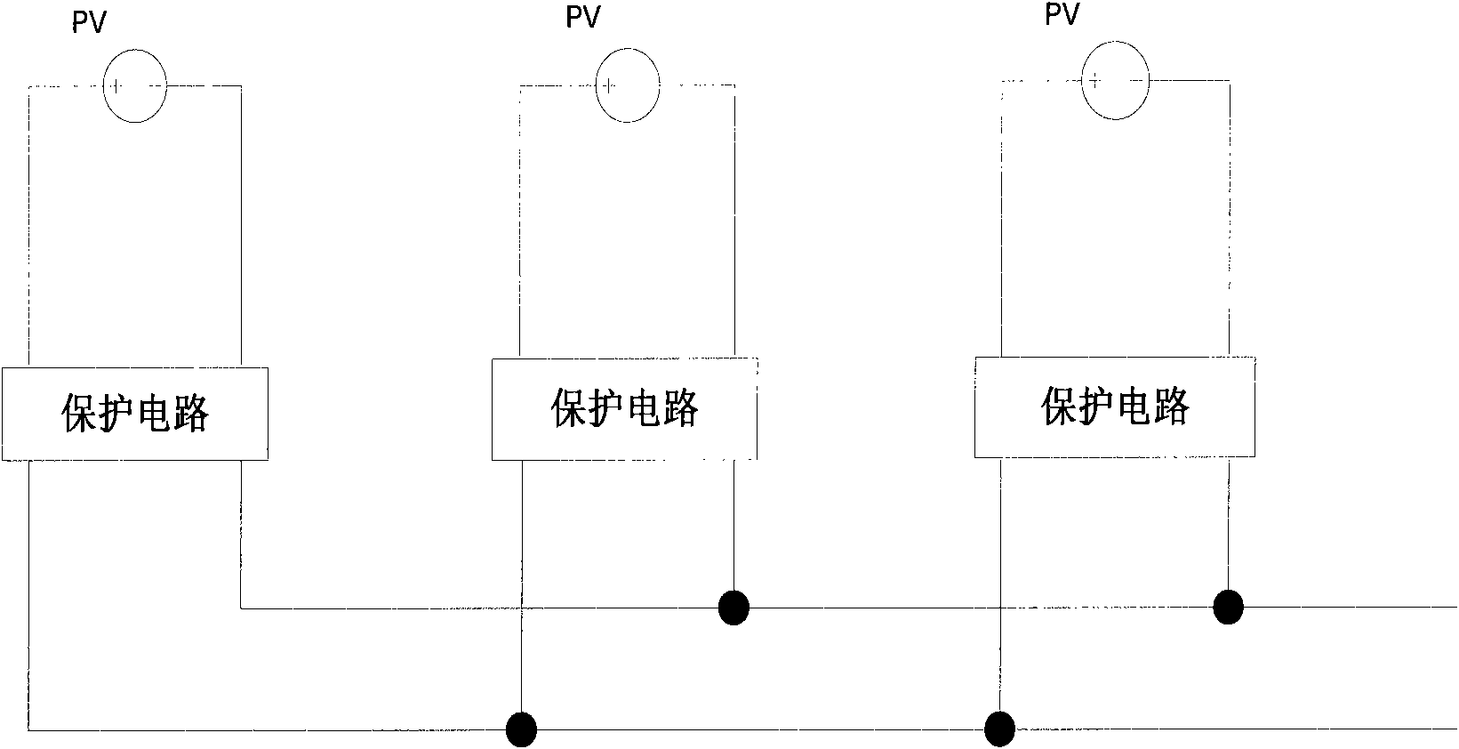
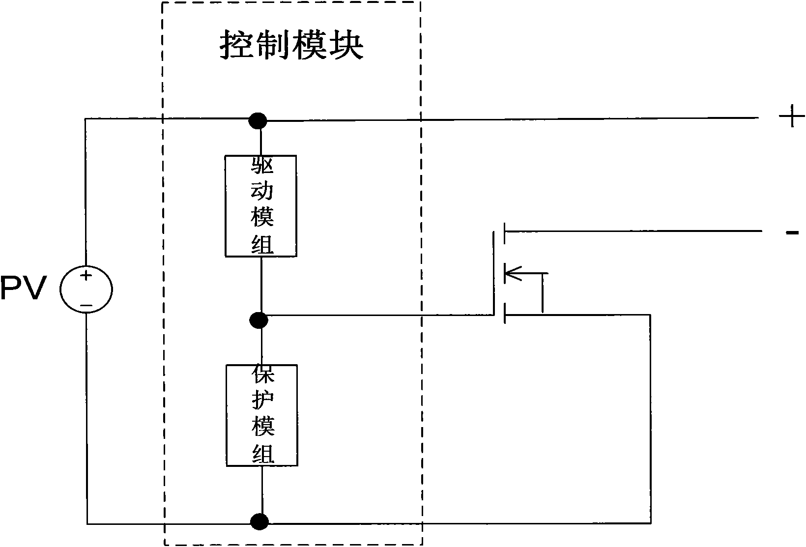
The invention discloses a parallel connection protection circuit for a solar module, which comprises a field effect transistor, a driving module and a protection module, wherein the field effect transistor is used for reverse current limiting; the driving module is used for driving the field effect transistor; the protection module is used for preventing the gate of the field effect transistor from high-voltage breakdown; the driving module is connected with the protection module to form a control module of the parallel connection protection circuit which is connected in parallel with the anode and cathode of the output of the solar module; the gate of the field effect transistor is connected between the driving module and the protection module, the source of the field effect transistor is connected with the cathode of the solar module, and the drain of the field effect transistor is forms the anode and cathode of the output of the protected solar module with the anode of the solar module; and the protection module may be a resistor, a diode string, a voltage stabilizing diode or the like. The novel parallel connection protection circuit provided by the invention greatly reduces the loss of a solar module protection circuit, improves the power generating capacity of a solar cell in the morning, in the evening and in cloudy and rainy days, is simply structured, highly universaland low in cost, and can promote the popularization of solar energy application.

Description

technical field [0001] The invention relates to a circuit design of a solar application module, in particular to a parallel protection circuit for preventing current backflow from damaging the solar module, increasing the output power of the solar module, and fault detection and indication modules. Background technique [0002] As a renewable new energy source, solar energy is more and more favored by people, and it is widely used in people's daily life and work. The most direct application is to convert solar energy into electrical energy. Solar cells receive the sun's radiant energy during the day and convert and output it. However, due to the weakening of light radiation in the morning, evening or rainy days, the output voltage of solar cells decreases. If there is no solar energy The protection circuit of the battery, the supplementary current stored by the battery or provided by other power sources in the output line will flow back to the solar battery, resulting in sho...

Claims


Application Information

Patent Timeline
Patent Type & Authority Applications(China)
IPC IPC(8): H02N6/00H02H9/04
CPCH01L31/02021Y02E10/56H02H3/003H02N6/00H02H9/04H02H9/041H02H3/18H01L31/00
Inventor 瞿磊王彤高海兵
Owner SUZHOU DONGLING VIBRATION TEST INSTR
Learn More