Process for producing sintered ore and sintering machine

A manufacturing method and technology of sintered ore, applied to furnaces, lighting and heating equipment, furnace types, etc., can solve the problems of prolonged high temperature retention time, reduced ventilation of combustion air, and inability to obtain mixed gas, etc., to achieve high cold strength, The effect of stable operation

Active Publication Date: 2011-07-20
JFE STEEL CORP
View PDF8 Cites 27 Cited by
  • Summary
  • Abstract
  • Description
  • Claims
  • Application Information

AI Technical Summary

Problems solved by technology

However, this method has the following problems: the concentration of gaseous fuel is high, so the amount of air (oxygen) to maintain combustion may be insufficient, and the combustion of the carbon material (coke) of the sintering raw material may be reduced, and the quality of the sintered ore cannot be improved.
However, if the mixed gas is injected without changing the coke ratio, the high temperature retention time will be prolonged and the maximum attained temperature will also rise, so a large amount of vitreous low-strength minerals will be generated, and the effect of mixed gas injection will not be obtained.
In addition, there is a danger of flammable mixed gas igniting and causing a fire, so it has not been put into practical use.
[0020] In addition, in the method described in Patent Document 4, since the amount of air (oxygen) is increased and the low-melting-point solvent and the carbon material are mixed, the combustion speed of combustible gas and coke is increased, but since the low-melting-point solvent and powder are simultaneously blown body, so there is a problem that the ventilation of the combustion air is reduced

Method used


Image

  • Process for producing sintered ore and sintering machine
  • Process for producing sintered ore and sintering machine
  • Process for producing sintered ore and sintering machine

Examples


Embodiment 1

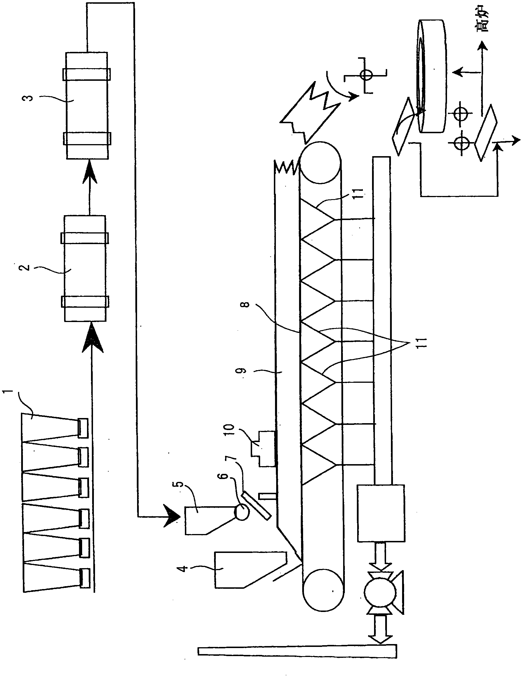
[0316] use Figure 28In the test panel shown, coke oven gas (C gas) diluted to 1 to 2.5% by volume was used as the gas fuel, and the other conditions were the same as the above-mentioned experimental conditions (paragraph 0099), and a carbon material (coke) containing 5% by mass was carried out. The sintered disk test of the sintered raw material. The result is shown in Figure 51 . As shown in the figure, when using C gas diluted according to the method of the present invention, once the concentration of C gas is increased, the width (thickness) of the combustion zone is significantly expanded, and while the yield and productivity are improved, the low-temperature strength (SI) can also be improved.

[0317] Example 1

[0318] Using propane diluted to 0.02% by volume to 0.5% by volume as the diluted gaseous fuel, the other conditions were the same as in Example 1, and a sintering pan test was performed on a sintering raw material containing 5% by mass of carbon material (...

Embodiment 3

[0320] use Figure 28 As shown in Table 14, the test disk shown in Table 14 was discharged from the top of the disk through cooling, and was charged into the charging layer composed of sintering raw materials whose coke powder content (outer number) varied in two levels: 4.9% by mass and 4.8% by mass. , Blow in coke oven gas (C gas) diluted to 1.0 volume % and 2.0 volume % (relative to air) two water concentration, and carry out sintering disc test (No.2~7). In addition, as a comparative example, the same sintering disk test was performed on an example (No. 1) in which the coke fines content (outer number) was 5.0% by mass and no diluent gas was injected. In addition, in this example, the total thickness of the sintered raw materials loaded in the test pan was 600 mm, and the sintered raw materials containing the above-mentioned coke powder were laminated in the upper 400 mm, and the return ore was laminated in the lower 200 mm.

[0321] In addition, when the position of the ...

Embodiment 4

[0331] The method for producing sintered ore according to the present invention is suitable for a DL-type sintering machine with a daily output of 20,000 tons. The length of the DL sintering machine used is 90m from the ignition furnace to the ore discharge part. At a position about 30m behind the ignition furnace of the sintering machine and a height of 500mm above the filling layer, a gas fuel supply device with the following structure is installed: Nine gaseous fuel supply pipes with a length of 15 m (the advancing direction of the table machine) are arranged in parallel in the advancing direction of the table machine, and 149 nozzles (a total of 1341 pieces) that eject gaseous fuel downwards are installed on each pipe at an interval of 100 mm. The nozzle ejects city gas as gas fuel into the air at high speed, and supplies diluted gas fuel with a city gas concentration of 0.8% by volume to the packed layer. In addition, the total thickness of the packed layer was laminated ...


PUM

PropertyMeasurementUnit
particle sizeaaaaaaaaaa
thicknessaaaaaaaaaa
thicknessaaaaaaaaaa

Abstract

A process for producing a sintered ore which comprises: a charging step in which a pallet traveling cyclically is charged with a raw sintering material comprising a powdery ore and a carbonaceous material to form a charge layer of the raw sintering material on the pallet; an ignition step in which the carbonaceous material present in the surface of the charge layer is ignited with an ignition furnace; a dilute-gaseous-fuel production step in which a gaseous fuel is supplied to the air present over the charge layer to dilute the fuel and thereby obtain a dilute gaseous fuel having a concentration not higher than the lower combustion limit concentration; and a combustion step in which the dilute gaseous fuel and air are sucked into the charge layer by the suction of a wind box disposed beneath the pallet to burn the dilute gaseous fuel in the sinter layer and, at the same time, burn the carbonaceous material contained in the charge layer with the aid of the air sucked into the charge layer, thereby produce a sinter cake.

Description

technical field [0001] The present invention relates to a method for producing sintered ore for a blast furnace raw material using a downward suction type belt (DL) sintering machine, and a sintering machine used in the method. Background technique [0002] Sintered ore, the main raw material for blast furnace ironmaking, is figure 1 Manufactured by the process shown. Raw materials include iron ore powder, recycled powder in ironworks, sinter under-sieve powder, limestone and dolomite and other secondary raw materials containing CaO, quicklime and other granulation aids, coke powder or anthracite, etc. These raw materials are cut out at a predetermined ratio from each hopper 1 to the conveyor belt. The cut out raw material is mixed and granulated by adding an appropriate amount of water with the cylinder mixer 2 etc., and is made into the quasi-particle sintered raw material which has an average particle diameter of 3.0 mm - 6.0 mm. The sintering raw materials are loaded ...

Claims


Application Information

Patent Timeline
Patent Type & Authority Applications(China)
IPC IPC(8): C22B1/20C22B1/16F27B21/08
CPCC22B1/205F27B21/06C22B1/20F27B19/00
Inventor 大山伸幸岩崎克博角谷秀纪长岛康雄竹生博
Owner JFE STEEL CORP
Why Eureka
Try Eureka