Mobile hot air distribution plate type fluidized bed dryer

A technology of fluidized bed drying and hot air distribution, which is applied in the direction of heating to dry solid materials, drying solid materials, drying, etc. Particles do not move, etc., to achieve uniform product moisture content, narrow distribution of material residence time, and small footprint

Active Publication Date: 2013-10-16
DALIAN UNIV OF TECH +1
View PDF8 Cites 0 Cited by
  • Summary
  • Abstract
  • Description
  • Claims
  • Application Information

AI Technical Summary

Problems solved by technology

As we all know, after pulverizing coking coal, lignite and oil shale, the particle size distribution obtained is relatively wide. If ordinary fluidized bed dryer is used for drying, large particles will not be fluidized, but small particles will be Entrained by the air flow out of the bed; or the small particles are fluidized while the large particles are stationary, resulting in a dead bed or blockage of the screen hole of the hot air distribution plate
At present, many kinds of fluidized bed drying equipment for coal drying have been developed, for example, the Chinese patent application name is "multi-chamber fluidized bed classification device" (CN1153633C), "coal drying method and drying device" ( CN1120872C), "moving clapboard fluidized bed" (CN101063059A), multi-stage combined fluidized-moving bed dryer and its drying method (CN1100445674C), a fluidized bed air separation and humidity control machine and a new air separation and humidity control process (CN101786080A) etc., although above-mentioned these fluidized bed dryers all have respective drying technical advantages, the hot air distribution plate of these drying equipments is all static, and all there is the local stagnation area of ​​material in varying degrees in the drying equipment, because Coking coal, lignite and oil shale are flammable and explosive materials, so the local residence time of the materials in the drying equipment is too long, and there are safety hazards such as combustion and explosion.

Method used


Image

  • Mobile hot air distribution plate type fluidized bed dryer
  • Mobile hot air distribution plate type fluidized bed dryer
  • Mobile hot air distribution plate type fluidized bed dryer

Examples


Embodiment Construction

[0016] The specific embodiments of the present invention will be described in detail below in conjunction with the technical solutions and accompanying drawings.

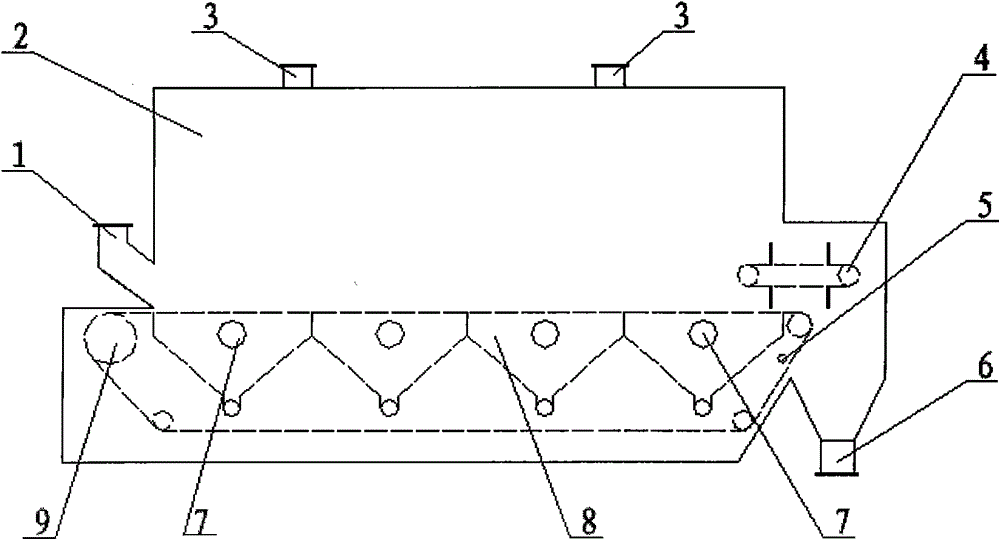
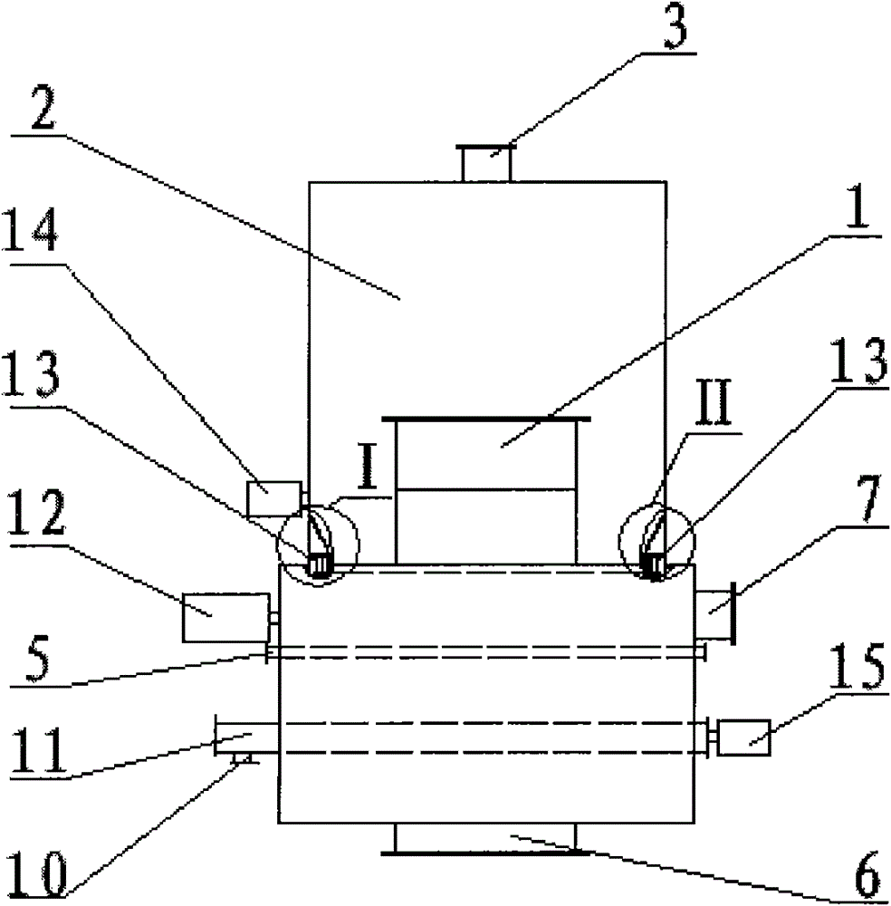
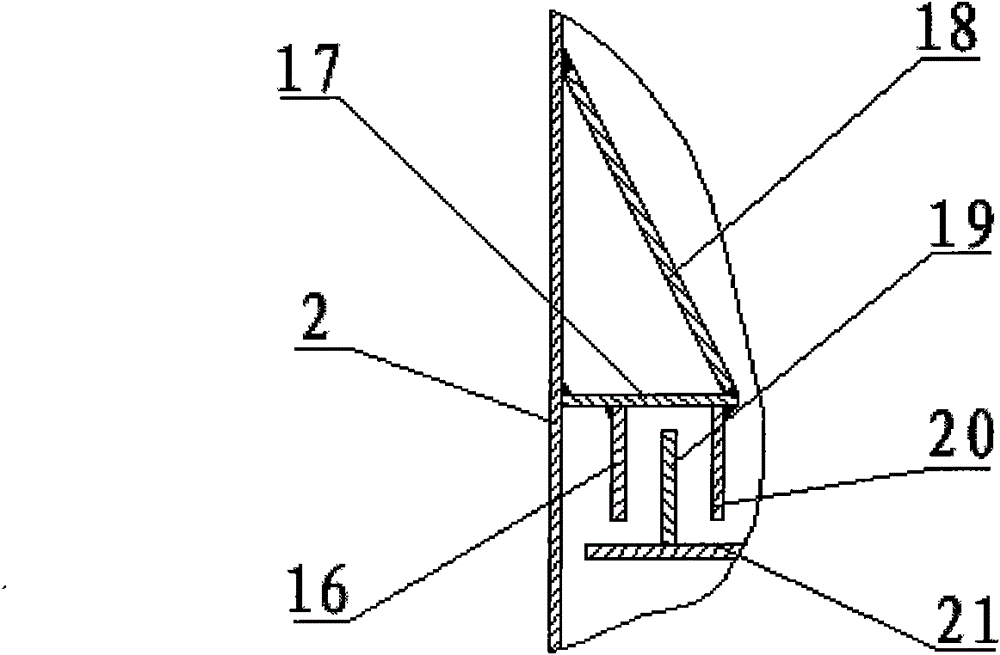
[0017] Such as Figure 1 to Figure 8 Shown, mobile hot blast distribution plate assembly 9 comprises hot blast distribution plate 21, driving wheel 22, driven wheel 25, tensioning pulley 23, roller chain 24 and mobile hot blast distribution plate driving device 12; Hot blast distribution plate 21 is made of many small The hot air distribution plate 28 is connected together, and the small hot air distribution plate 28 is provided with oblique circular channels, the diameter of which is 1 to 4 mm, the opening rate is 2% to 15%, and the angle between the oblique channels and the vertical direction is 0 to 10%. 65°, the small hot air distribution plate 28 and the roller chain 24 are fastened together with bolts; the horizontal movement speed of the moving hot air distribution plate is 20-300mm / s, and by adjusting the mo...


PUM


Abstract

The invention discloses a mobile hot air distribution plate type fluidized bed dryer, and belongs to the technical field of drying equipment and engineering. The dryer is characterized by comprising a box body, a hot air distribution chamber, a mobile hot air distribution plate assembly, a mobile weir plate assembly, a material seal type hot air sealing structure, an air knife, a hot air inlet, awaste gas outlet, a wet material inlet, a product outlet and the like. A drying method using the drying equipment comprises the following steps of: adding a wet material onto a hot air distribution plate through the wet material inlet, performing fluidized drying on fine granules by means of hot air in a mobile hot air distribution plate type fluidized bed, drying coarse granules and the mobile hot air distribution plate together while moving, discharging the dried qualified product from the product outlet, and exhausting the waste gas from the waste gas outlet. The dryer has the advantages of simple structure, easiness in manufacture, small floor area, narrow material residence time distribution, uniform water content of the product, and safety and convenience in the operation process.

Description

technical field [0001] The invention belongs to the field of drying equipment and engineering technology, and relates to drying equipment for inflammable and explosive materials such as coking coal, lignite and oil shale. Background technique [0002] There are many drying methods for flammable and explosive materials such as coking coal, lignite and oil shale. According to the way the drying medium contacts the wet material, it can be divided into two categories: direct heating drying and indirect heating drying. Since coking coal, lignite and oil shale are not afraid of flue gas pollution and do not chemically react with flue gas, the most commonly used in industry is a direct heating convective dryer with flue gas as the drying medium, such as airflow dryer, rotary drum dryers, rotary tube dryers and fluidized bed dryers. The airflow dryer has simple structure, large processing capacity and short drying time, but the system resistance is large, and it is difficult to ob...

Claims


Application Information

Patent Timeline
Patent Type & Authority Patents(China)
IPC IPC(8): F26B3/084F26B17/18
Inventor 于才渊戴云峰王宝和王路敏毕佶
Owner DALIAN UNIV OF TECH
Why Eureka
Try Eureka