Tubeless heat exchanger and waste heat recovery system

A waste heat recovery system and heat exchanger technology, which can be used in heat exchanger types, indirect heat exchangers, regenerative heat exchangers, etc. problems, to achieve the effect of reducing volume and steel consumption, reducing equipment cost and improving heat exchange efficiency

Inactive Publication Date: 2011-12-21
HUNAN TIANSHUILAN ENERGY TECH
View PDF6 Cites 10 Cited by
  • Summary
  • Abstract
  • Description
  • Claims
  • Application Information

AI Technical Summary

Problems solved by technology

Due to the limitations of the structure of the air preheater and the heat transfer mechanism, these traditional tube shell and regenerative tubeless heat exchangers have always had the following problems and have not been resolved for a long time: (1) The heat transfer efficiency is not high, no The metal or glass consumption of the tube heat exchanger is huge, the equipment is heavy, and the manufacturing, operation and maintenance costs are high; (2) The air leakage is large (8% to 30%), which increases the power consumption of the blower by more than 15 to 30%. And it seriously affects the operation output of the unit; (3) It is very easy to cause dust, blockage and low-temperatur...

Method used


Image

  • Tubeless heat exchanger and waste heat recovery system
  • Tubeless heat exchanger and waste heat recovery system
  • Tubeless heat exchanger and waste heat recovery system

Examples


Embodiment approach 1

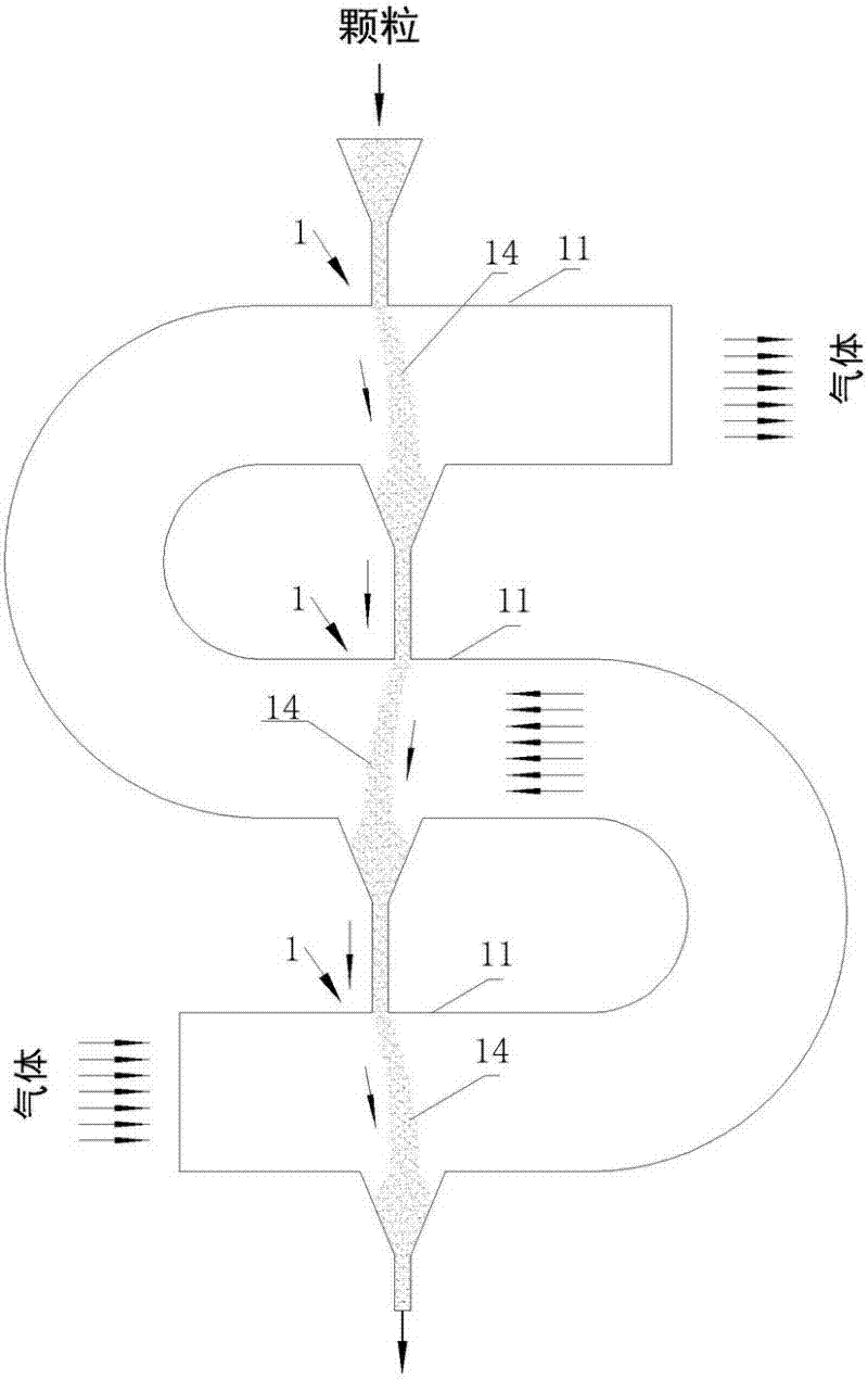
[0068] Embodiment 1: It is a serpentine elbow type three-stage waste heat recovery system, see Figure 7-Figure 12 .

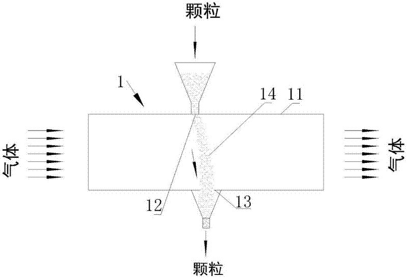
[0069] It can be used when the boiler or other reactor tail gas discharge pipes and preheating air pipes have sufficient layout space in the height direction Figure 7 with Figure 12 One of the tubeless heat exchangers used in these systems are serpentine tubeless heat exchangers, of which Figure 7 It is shown that the air tubeless heat exchanger B is arranged vertically below the flue gas tubeless heat exchanger A and is vertically connected in series with the flue gas tubeless heat exchanger A. The high-temperature flue gas enters from the lower part of the flue gas tubeless heat exchanger A and is discharged from the top. The particles naturally fall from the top hopper by gravity to form a three-stage particle curtain, and exchange heat with the rising hot flue gas in turn during the falling process. The three-stage After the heat exchange is complete...

Embodiment approach 2

[0075] Embodiment 2: It is a four-stage waste heat recovery system with a serpentine bend, see Figure 13-Figure 18

[0076] When the tail gas discharge pipes and preheating air pipes of boilers or other reactors have sufficient layout space in the height direction and the exhaust gas temperature is high, a four-stage or five-stage waste heat recovery system with serpentine bends can be used, such as Figure 13-Figure 18 shown, with Figure 7 to Figure 12 Compared with the serpentine elbow type three-stage waste heat recovery system shown, it can be seen that the tubeless heat exchanger in this embodiment adopts a serpentine elbow type tubeless heat exchanger with four particle curtain heat exchange units. The number of heat exchange stages is increased, and other components, particle conveying device 5 (pneumatic or mechanical conveying) and its reliability to the system, as well as the flexibility of maintenance and operation, etc. resemblance. I won't go into details her...

Embodiment approach 3

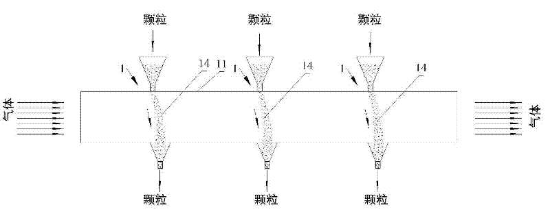
[0077] Embodiment 3: It is a horizontal straight pipe three-stage waste heat recovery system, see Figure 19-Figure 24 .

[0078] When the exhaust temperature of boiler or other reactor is not very high and it is arranged horizontally up and down in the same vertical plane as the air pipe, such as Figure 19-Figure 24 The three-stage waste heat recovery system shown. Compared with the serpentine curved three-stage waste heat recovery system, the particle transfer between the particle curtain heat exchange units at all levels in the horizontal straight pipe three-stage waste heat recovery system is more complicated, and the number of particle transfer devices required is larger.

[0079] from Figure 19 It can be seen that this is a three-stage parallel system. The flue gas tubeless heat exchanger A and the air tubeless heat exchanger B of this system are both in the form of horizontal straight tubes. The particle curtains of the flue gas tubeless heat exchanger exchange heat...


PUM

PropertyMeasurementUnit
Particle sizeaaaaaaaaaa

Abstract

The invention discloses a tubeless heat exchanger and a waste heat recovery system. The tubeless heat exchanger is connected by at least one particle curtain heat exchange unit, and the particle curtain heat exchange unit has a gas channel in the shape of a horizontal straight tube. The gas passage is provided with a particle inlet and a particle outlet, and the particles are used as heat exchange medium to form a particle curtain from the particle inlet to the particle outlet, and the particles are inert solid particles. The waste heat recovery system includes a tubeless heat exchanger that feeds flue gas, which is called a flue gas tubeless heat exchanger, and a tubeless heat exchanger that feeds air is called an air tubeless heat exchanger. The conveying device is connected with the flue gas tubeless heat exchanger, the air tubeless heat exchanger and the particle conveying device through a particle pipeline. The tubeless heat exchanger and waste heat recovery system of the present invention have high heat exchange efficiency, low equipment consumables, low operation and maintenance costs, good sealing performance, and low energy consumption, and are suitable for various industries with high exhaust temperature and waste heat utilization value equipment and reactors.

Description

technical field [0001] The invention mainly relates to the technical field of high-efficiency heat exchange and waste heat recovery and utilization, and is especially suitable for various industrial equipment and reactors with high exhaust gas temperature and waste heat utilization value, including industrial boilers, power station boilers, various furnaces, and smelting furnaces. , Sintering furnace, heating furnace and waste incineration device, etc. technical background [0002] my country has an astonishing number of various industrial boilers, power plant boilers, metallurgical furnaces and various heating furnaces. The primary energy consumed by these boilers and furnaces accounts for more than two-thirds of my country's fossil fuels. Due to the design defects of these boilers and kilns and the characteristics of the fuel used during operation, operating conditions and equipment defects (such as heat transfer efficiency decline), the exhaust temperature of most boilers...

Claims


Application Information

Patent Timeline
IPC IPC(8): F28C3/14F28D19/02F23L15/00
CPCF28C3/14
Inventor 陈冬林秦小林
Owner HUNAN TIANSHUILAN ENERGY TECH
Why Eureka
Try Eureka