High-stability optical fiber Fabry-Perot pressure sensor packaged without glue and manufacturing method
A technology of pressure sensor and glue-free packaging, which is applied in the application of optical methods for fluid pressure measurement, measurement of fluid pressure, measurement of fluid pressure through electromagnetic components, etc., which can solve the problem that it is not suitable for mass production, the temperature and humidity characteristics of the sensor are unfavorable, and it cannot be used. The mechanical properties of monocrystalline silicon wafers and other issues can achieve the effect of improving sensing accuracy and reducing costs
- Summary
- Abstract
- Description
- Claims
- Application Information
AI Technical Summary
Problems solved by technology
Method used
Image
Examples
Embodiment 1
[0038] Embodiment 1: The specific implementation of the first optical fiber Fabry-Perot pressure sensor
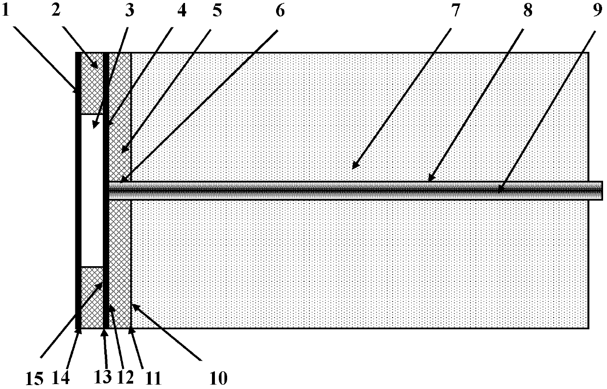
[0039] Such as figure 1 As shown, the fiber optic Fabry-Perot pressure sensor consists of a sensor head, a sensor body 7 and a transmission fiber 9 . The sensor head consists of a four-layer structure, the first layer is the first monocrystalline silicon wafer 1, the second layer is the first Pyrex glass wafer 2, the third layer is the second monocrystalline silicon wafer 4, and the fourth layer is the second Pyrex glass wafer. Glass sheet 5. The first single crystal silicon wafer 1 is used as an elastic diaphragm to feel the pressure, and the rear surface 14 of the first single crystal silicon wafer simultaneously constitutes the first reflection surface of the Fabry-Perot cavity; the first Pyrex glass wafer 2 is annular , a through hole 3 is processed in the middle, and the thickness of the first Pyrex glass sheet 2 determines the initial length of the Fabry-Perot cavi...
Embodiment 2
[0046] Embodiment 2: The specific implementation of the second optical fiber Fabry-Perot pressure sensor
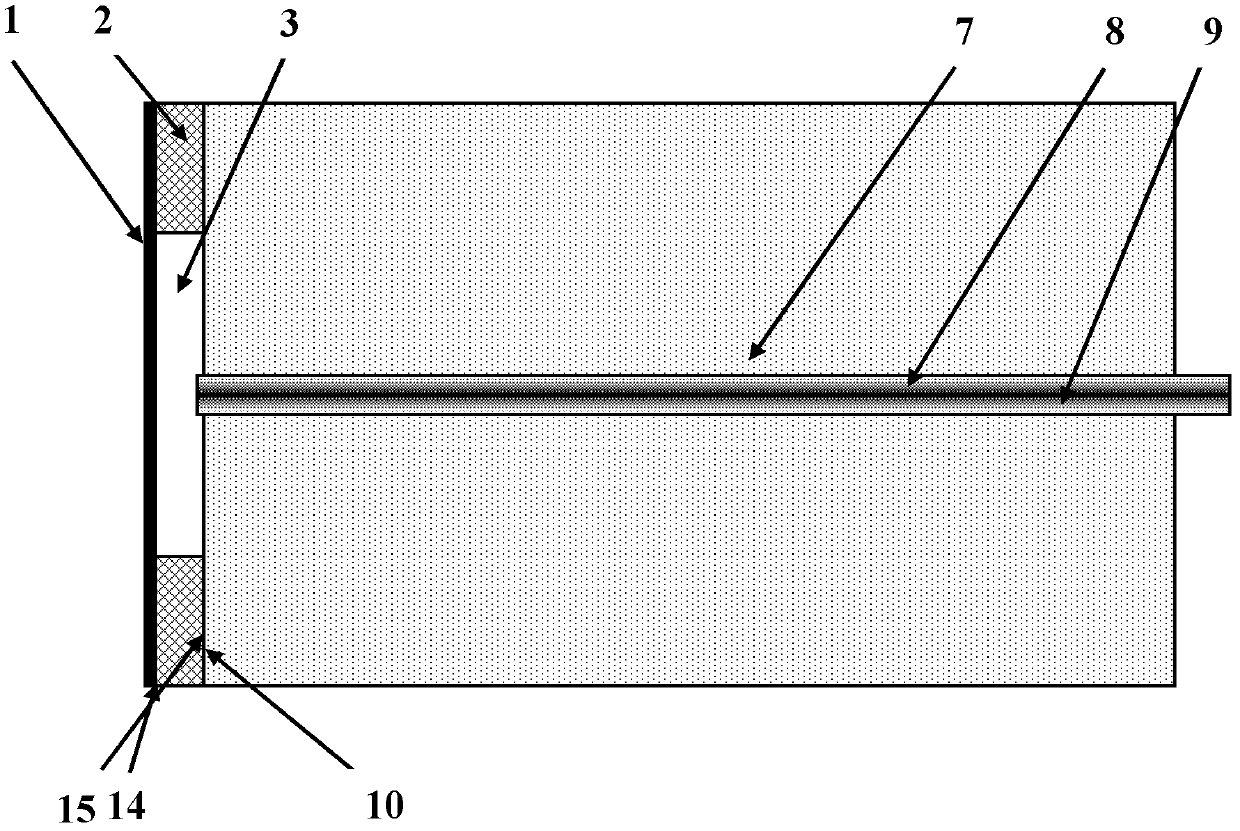
[0047] Such as figure 2 As shown, the fiber optic Fabry-Perot pressure sensor consists of a sensor head, a sensor body 7 and a transmission fiber 9 . The sensor head consists of a two-layer structure, the first layer is a single crystal silicon wafer 1, and the second layer is a Pyrex glass wafer 2. The monocrystalline silicon wafer 1 is used as an elastic diaphragm to feel the pressure, and the inner surface 14 of the monocrystalline silicon wafer simultaneously constitutes the first reflection surface of the Fabry-Perot cavity; the Pyrex glass wafer 2 is processed with a through hole 3, the thickness of which is determines the initial length of the Fabry-Perot cavity. The monocrystalline silicon wafer 1 is anodically bonded on the Pyrex glass wafer 2, and the outer surface of the monocrystalline silicon wafer 1 of the sensor head is roughened by using a Nd:YAG laser ...
Embodiment 3
[0052] Embodiment 3: Cavity length demodulation of fiber optic Fabry-Perot pressure sensor
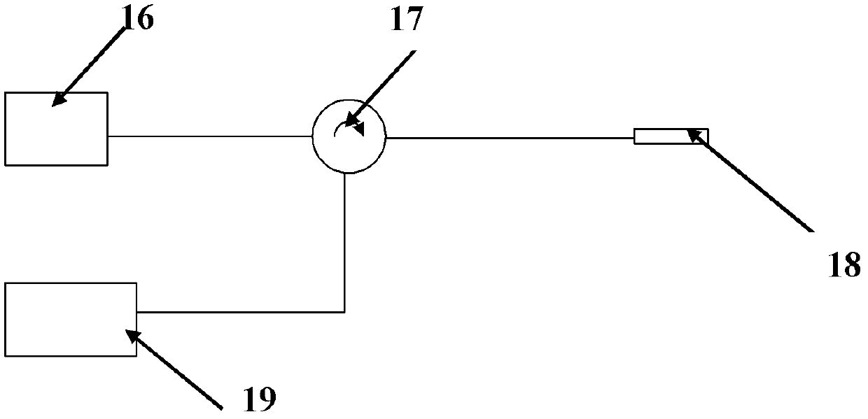
[0053] The sensing system of fiber optic Fabry-Perot pressure sensor such as image 3 As shown, the light emitted by the cavity length demodulated broadband light source 16 enters the sensor 18 through the circulator 17 , passes through the Fabry-Perot cavity of the sensor, and then enters the spectrometer 19 through the circulator 17 . The spectrum returned by the sensor is obtained by scanning the spectrometer 19, and the cavity length information of the optical fiber Fabry-Perot pressure sensor can be obtained by calculating the peak position of the spectral envelope, and the relationship between the Fabry-Perot cavity length and its interference spectrum The relationship is: where d is the Fabry-Perot cavity length λ 1 ,λ 2 represent the two peak positions of the spectral envelope, respectively. The Fabry-Perot cavity length can be converted into pressure information, and the ...
PUM
| Property | Measurement | Unit |
|---|---|---|
| diameter | aaaaa | aaaaa |
| diameter | aaaaa | aaaaa |
| diameter | aaaaa | aaaaa |
Abstract
Description
Claims
Application Information
 - R&D
- Intellectual Property
- Life Sciences
- Materials
- Tech Scout
- Unparalleled Data Quality
- Higher Quality Content
- 60% Fewer Hallucinations
Browse by: Latest US Patents, China's latest patents, Technical Efficacy Thesaurus, Application Domain, Technology Topic, Popular Technical Reports.
© 2025 PatSnap. All rights reserved.Legal|Privacy policy|Modern Slavery Act Transparency Statement|Sitemap|About US| Contact US: help@patsnap.com


