
Air intake system for generating power by using cement kiln bypass flue gas waste heat

A technology for bypass ventilation and flue gas waste heat, which can be used in waste heat treatment, lighting and heating equipment, and process efficiency improvement.

Active Publication Date: 2013-08-21
大连九五高科新能源发展有限公司
View PDF5 Cites 0 Cited by
  • Summary
  • Abstract
  • Description
  • Claims
  • Application Information

AI Technical Summary

Problems solved by technology

The total processing capacity of the two sets of kiln gas purification systems will greatly exceed the original kiln gas volume, and a huge price will be paid in terms of infrastructure investment, floor area, power consumption, operation and maintenance costs
2) Due to the high viscosity of the exhaust gas dust in the kiln tail smoke chamber, it is easy to cause the blockage of the exhaust gas pipeline and the exhaust gas cooling equipment of the bypass ventilation, which seriously affects the normal operation of the bypass ventilation system
3) The heat recovery rate of kiln gas in the bypass ventilation system is low, which pollutes the environment and wastes heat energy
However, during an industrial experiment in a domestic cement plant, it was found that due to the high temperature of the flue gas in the kiln tail smoke chamber and the high viscosity of the flue gas dust, problems such as skinning and blockage of the bypass air intake pipeline are prone to occur, so the waste heat of the bypass air release The boiler could not be put into use, resulting in the failure of the bypass ventilation waste heat power generation technology to be implemented smoothly

Method used


Image

  • Air intake system for generating power by using cement kiln bypass flue gas waste heat
  • Air intake system for generating power by using cement kiln bypass flue gas waste heat
  • Air intake system for generating power by using cement kiln bypass flue gas waste heat

Examples


Embodiment 1

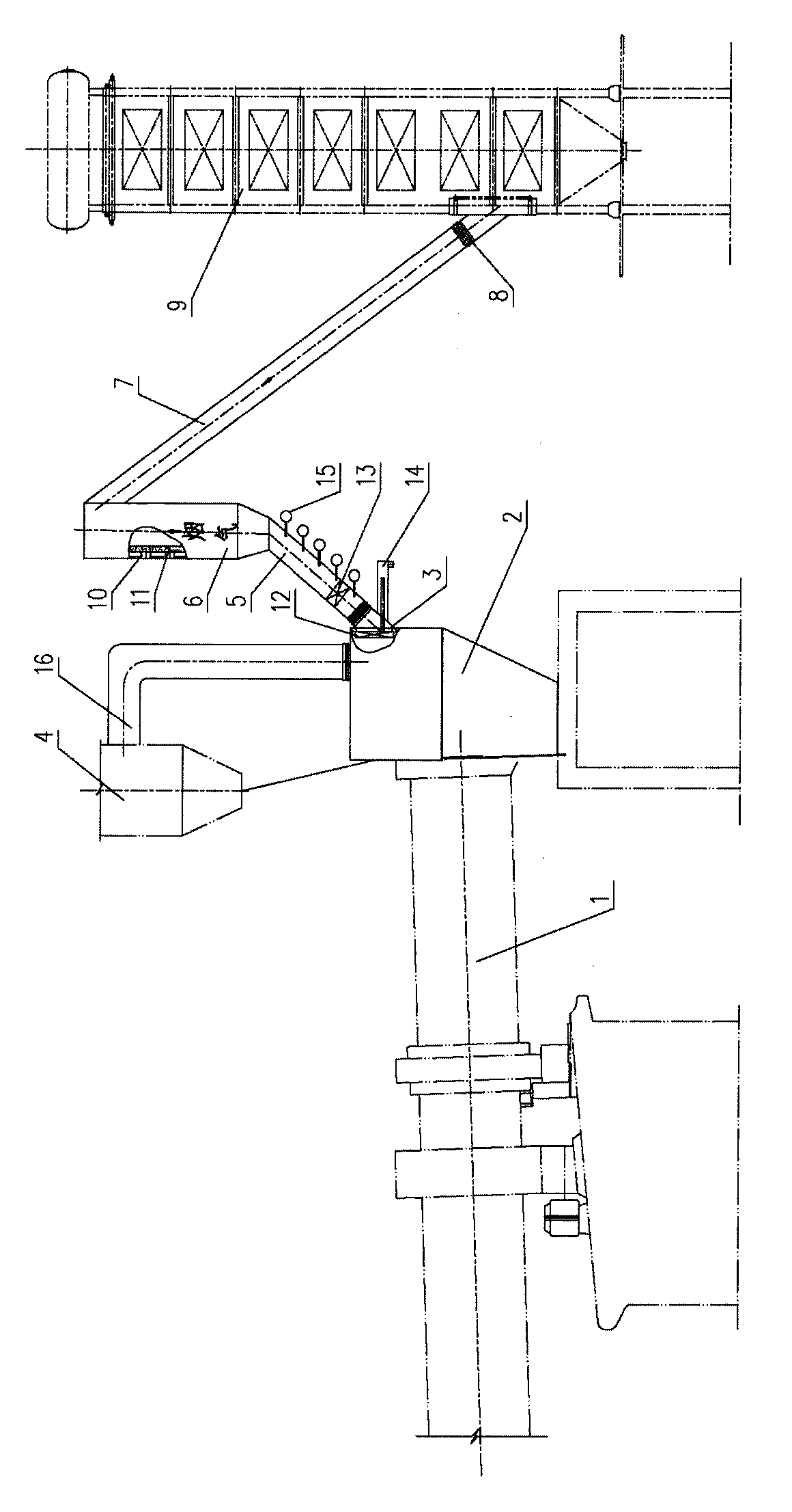
[0036] Such as figure 1As shown, an air intake is set on the side wall of the kiln tail smoke chamber, and a flexible ash blocking device is installed at the air intake. The flexible ash blocking device is a chain curtain or a spring curtain or a reed shutter. When taking the flexible ash-retaining device of the tuyere, part of the sticky dust sticks on the flexible ash-retaining device. The dust removal device arranged here can regularly remove the dust bonded to the flexible dust retaining device. A flue air valve is also set on the air taking pipe I to open the bypass flue gas. Multiple groups of air cannons are installed along the length direction of the wall surface of the air intake pipe I, which can remove the dust settled on the wall surface of the air intake pipe I, and make the dust fall into the rotary kiln. The top of the air pipe I is connected to the air pipe II, and the air pipe II is placed vertically. The flow velocity of the flue gas in the air pipe II is ...

Embodiment 2

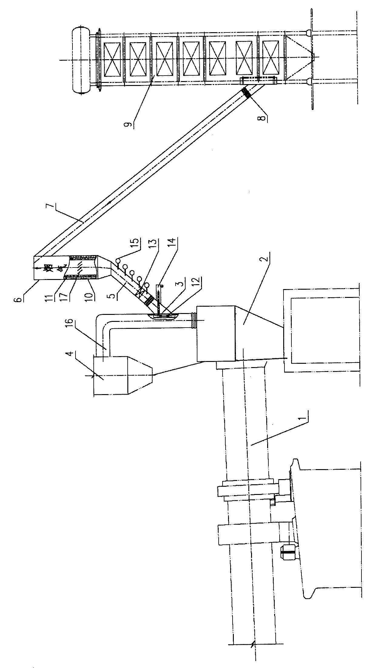
[0038] Such as figure 2 As shown, an air intake is set on the side wall of the ascending flue, and a flexible device is installed at the air intake. When the high-temperature exhaust gas from the bypass passes through the flexible device of the air intake, part of the sticky dust will stick to the flexible device. The dust removal device arranged here can regularly remove the dust adhered to the flexible device. The flue gas passes through the air intake pipe I connected to the air intake, and an expansion device is installed between the air intake pipe I and the air intake of the bypass air outlet, and a smoke damper is also installed on the air intake pipe I to perform bypass air release The opening of the smoke. A plurality of groups of air cannons are arranged in the length direction of the wall surface of the air intake pipe I to remove the settled dust on the wall surface of the air intake pipe I. The other end of the air pipe I is connected to the air pipe II, and th...

Embodiment 3

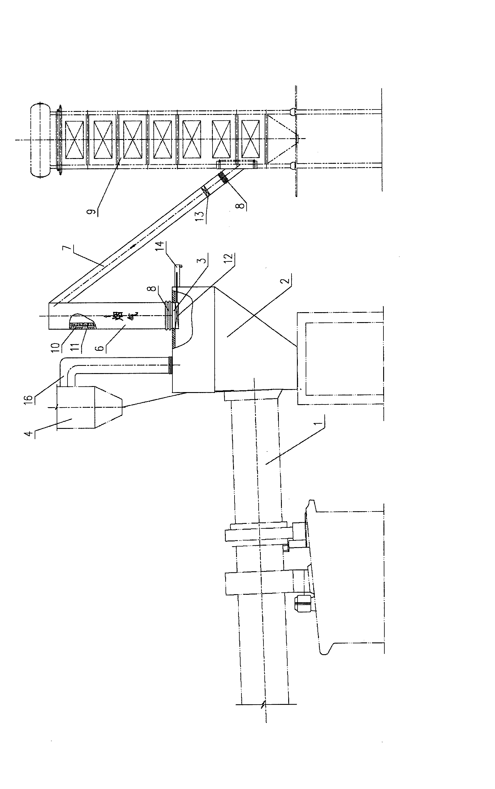
[0040] Such as image 3 As shown, an air intake is set on the top of the kiln tail smoke chamber, and a flexible device is installed at the air intake. When the bypass high-temperature flue gas passes through the flexible device at the air intake, part of the sticky dust sticks on the flexible device. The cleaning device at the location can regularly remove the dust stuck on the flexible device. The flue gas passes through the air intake pipe II vertically connected to the air intake port. The average flow velocity of the flue gas in the air intake pipe II is 7m / s, and the large-sized particles in the flue gas settle here and fall directly to the kiln tail smoke chamber Among them, the top of the air intake pipe II is closed, and an expansion device is set between the air intake pipe II and the air intake to prevent damage caused by the expansion of the pipeline. Open on the side wall near the top of the air intake pipe II and communicate with the air intake pipe III, and the...


PUM


Abstract

The invention discloses an air intake system for generating power by using cement kiln bypass flue gas waste heat. The air intake system comprises a rotary kiln, a kiln tail smoke chamber, a lifting flue, a preheater and a kiln tail bypass waste heat boiler; the side wall or the top of the kiln tail smoke chamber or the side wall of the lifting flue is provided with an air intake; the air intake is connected with a smoke inlet of the kiln tail bypass waste heat boiler through an air intake pipe; the air intake pipe consists of three sections of pipes, namely an air intake pipe I, an air intake pipe II and an air intake pipe III; the air intake pipe I is obliquely mounted upwards, the bottom end of the air intake pipe I is connected with the air intake, and the top end of the air intake pipe I is connected with the vertical air intake pipe III; the top end of the air intake pipe II is closed, and the side wall at the top end of the air intake pipe II is communicated with the air intake pipe III oblique downwards; and the bottom end of the air intake pipe III is communicated with the smoke inlet of the kiln tail bypass waste heat boiler. The air intake system can effectively solve the problem of ash blockage of a bypass air intake pipeline, and has the advantages of reasonable structure, convenience for assembly and disassembly, high efficiency, high safety, simple cleaning process, low ash blockage rate and the like.

Description

technical field [0001] The invention relates to a cement kiln bypass air discharge and air intake device, in particular to a flue gas air intake device used in the process of cement kiln bypass air discharge and waste heat power generation. Background technique [0002] In the cement production process, potassium, sodium, chlorine, and sulfur elements in raw materials and fuels are the interference factors that can stabilize the production of the new dry process cement kiln and affect the quality of cement products. Excessive presence of them may easily cause the kiln tail or preheater, smoke There are problems such as crusting and clogging in the road, and in severe cases, it will cause clogging, affect the normal operation of the cement firing system, and also reduce the quality of cement. [0003] It is known that the bypass ventilation technology has been widely used at home and abroad, and the bypass ventilation technology is mainly used in the cement production process...

Claims


Application Information

Patent Timeline
Patent Type & Authority Patents(China)
IPC IPC(8): F27D17/00
CPCY02P10/25
Inventor 唐金泉金万金孙明朗刘晓江
Owner 大连九五高科新能源发展有限公司
Learn More