Light splitting device and method for improving spectrum probing range

A spectroscopic device and spectral detection technology, applied in spectrometry/spectrophotometry/monochromator, measuring device, radiation pyrometry, etc., can solve the problem of uneven detector distribution, low detector space utilization, Increase measurement time and other issues to achieve the effect of eliminating overlapping interference between levels, saving measurement time, and uniform level distribution

Active Publication Date: 2012-07-04
FOCUSED PHOTONICS
View PDF7 Cites 12 Cited by
  • Summary
  • Abstract
  • Description
  • Claims
  • Application Information

AI Technical Summary

Problems solved by technology

[0012] 3. If image 3 As shown, with the wavelength from short-wavelength to long-wavelength, the distribution of spectral spectra on the detector is severely uneven, resulting in low space utilization of the detector
[0013] 4. Usually, if you need to collect the spectrum in the deep ultraviolet band, you need two exposures, which increases the moving parts and increases the measurement time

Method used


Image

  • Light splitting device and method for improving spectrum probing range
  • Light splitting device and method for improving spectrum probing range
  • Light splitting device and method for improving spectrum probing range

Examples


Embodiment 1

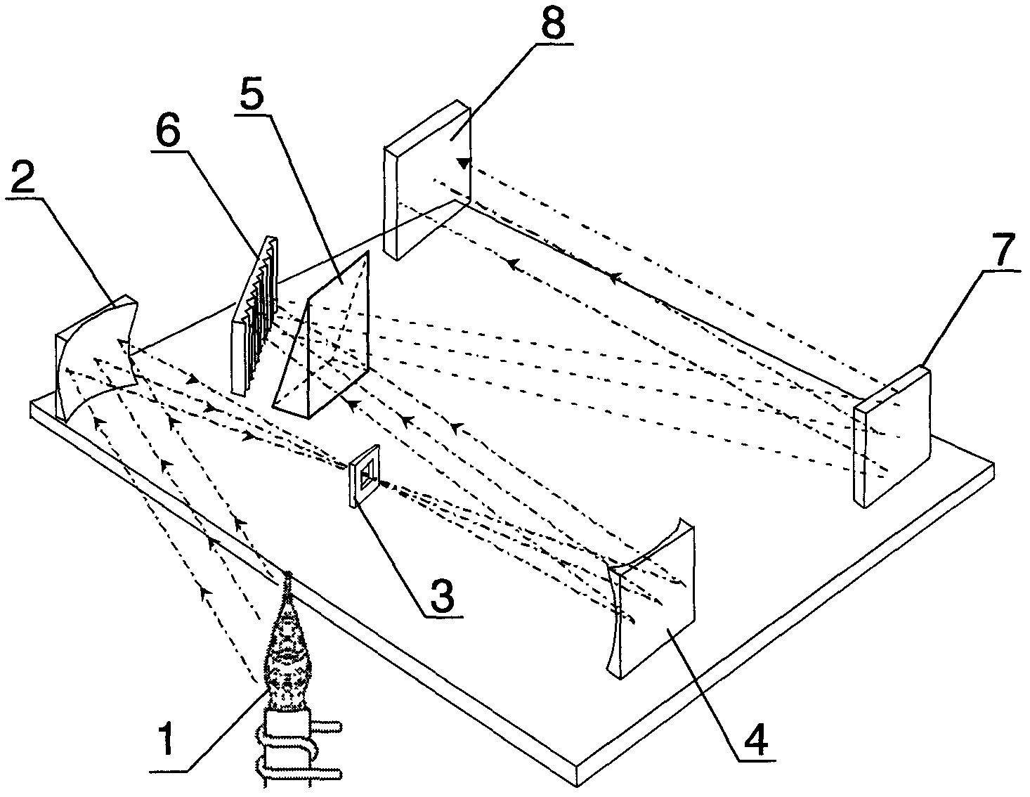
[0060] Figure 4 The basic structure diagram of the spectrum analysis system of the embodiment of the present invention is schematically given. Such as Figure 4 As shown, the spectral analysis system includes:

[0061] A light source 11, the light source is inductively coupled plasma, spark direct reading light source, flame, glow discharge, microwave plasma, ultraviolet lamp, etc.

[0062] A lighting device, the lighting device includes a collecting mirror 12 , an incident slit 13 and a collimating mirror 14 .

[0063] A spectroscopic device, the spectroscopic device is used to split and detect the measurement light emitted by the light source, please refer to the description in the next part for details.

[0064] An analysis unit, the analysis unit uses absorption spectrum analysis technology or emission spectrum analysis technology to analyze the signal transmitted from the spectroscopic device. The analysis unit is a prior art in this field, and will not be repeated h...

Embodiment 2

[0091] Figure 6 The basic structural diagram of the spectral analysis system in Example 1 of the present invention is schematically given. Such as Figure 6 Shown, different from embodiment 1 is:

[0092] 1. The prisms with different wedge angles are in the optical path at different times, and the prisms with different wedge angles are driven by the mobile module.

[0093] 2. The processing unit processes the spectra received by the detection unit when prisms with different wedge angles are in the optical path, such as combining the spectra acquired twice before and after by software into a complete spectrum.

[0094] A kind of spectroscopic analysis method, different from embodiment 1 is:

[0095] 1. The prisms with different wedge angles are in the optical path at different times, and the prisms 25 and 29 with different wedge angles are specifically driven by the mobile module. The detection unit requires two spectra acquisitions.

[0096] 2. The processing unit proces...

Embodiment 3

[0098] According to the application example of the spectral analysis system and method in the metallurgical industry of Embodiment 1 of the present invention, according to the national standard (GB / T20125-2006), it is necessary to use an inductively coupled plasma-atomic emission spectrometer to identify low-alloy steel. The elements are silicon, manganese, phosphorus, nickel, chromium, molybdenum and the like. In this application example, the spectral lines suitable for detection of phosphorus and other elements are in the deep ultraviolet band, for example, P: 153.592nm. Therefore, the detection range of the spectroscopic device in the analysis system should be extended to the deep ultraviolet band, and the detection range covers [130nm, 1050nm].

[0099] In this application example, the light source uses inductively coupled plasma to excite steel samples of different grades to be tested. The wedge angle of the small wedge angle prism in the second light splitting unit is 2...


PUM


Abstract

The invention provides a light splitting device for improving the spectrum probing range, which includes a first light splitting unit, a second light splitting unit, a detection unit and a processing unit, wherein the first light splitting unit is used for light splitting of measured light, and the wave length of the measured light covers the range of [lambda1, lambda 2]; the second light splitting unit includes chromatic dispersion component(s) Mi used for the light splitting of measured light before or / and after passing by the first light splitting unit and having different light splitting capabilities, wherein I equals to 1, 2 to N, and N equals to or is lager than 2, and the chromatic dispersion direction of the first and the second light splitting units are mutually vertical; the detection unit is used for converting optical signals of the received measured light passing by the first light splitting unit or the chromatic dispersion component(s) Mi into electrical signals Ii respectively, and transmitting the electrical signals to the processing unit, wherein I equals to 1, 2 to N, and N equals to or is lager than 2; and the processing unit is used for combining the received electrical signals Ii, so as to obtain the light intensity distribution of the measured light in the range of [lambda1, lambda 2], wherein I equals to 1, 2 to N, and N equals to or is lager than 2. The light splitting device provided by the invention has the advantages of excellent stability, simplicity in installation and debugging, excellent maintainability, low cost and the like.

Description

technical field [0001] The invention relates to the spectroscopic separation of polychromatic light, in particular to a spectroscopic device and method capable of significantly improving the spectrum detection range. Background technique [0002] A spectrometer is a device that continuously distributes and detects the collected spectra. At present, common spectrometer structures include Czerny-Turner structure, Paschen-Runge structure, flat-field concave grating spectroscopic system, echelle grating two-dimensional spectroscopic system, etc. The echelle two-dimensional spectroscopic system has the advantages of small size and high resolution, so it is widely used in occasions that require high resolution. [0003] figure 1 Schematically gives the basic structure diagram of the conventional échelle grating two-dimensional spectroscopic system, such as figure 1 As shown, the spectroscopic system includes a light source 1 , a collector mirror 2 , an entrance slit 3 , a colli...

Claims


Application Information

Patent Timeline
Patent Type & Authority Applications(China)
IPC IPC(8): G01N21/31G01J3/02G02B27/10
Inventor 俞晓峰顾海涛吕全超李萍王健
Owner FOCUSED PHOTONICS
Why Eureka
Try Eureka