

P-I-N type polymer solar cell and preparation method thereof
A P-I-N, solar cell technology, applied in the field of polymer solar cells, can solve the problems of no anti-solvent, can not achieve reduction of carrier recombination, etc., to reduce recombination, improve anti-solvent performance, and good experimental repeatability Effect
- Summary
- Abstract
- Description
- Claims
- Application Information
AI Technical Summary
Problems solved by technology
Method used
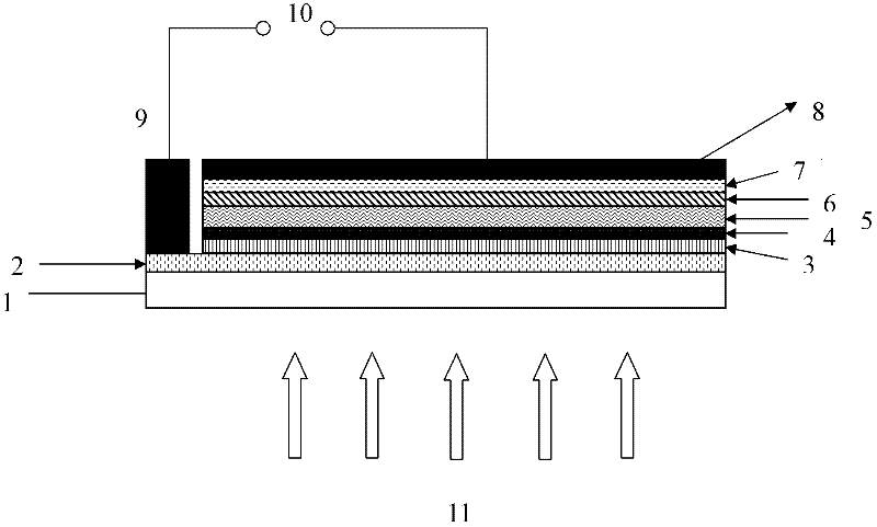
Image

Examples
Embodiment 1
[0034] Embodiment 1 (comparative example of embodiment 3)
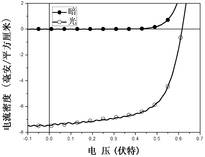
[0035] The transparent conductive glass sputtered with indium tin oxide (ITO) was ultrasonically cleaned with detergent, deionized water, acetone, and isopropanol in sequence, dried with nitrogen, and spin-coated with PEDOT:PSS aqueous solution at 2000 rpm, 150 ° C Bake for 15 minutes and cool naturally to obtain an anodic finishing layer. Combine 10mg / mL of P088 with PC 60 A mixed solution of BM 1:1.3 (mass ratio) (dropped with 3% additive 1-8 diiodooctane) was directly spin-coated on the above-mentioned anode modification layer at a rotational speed of 1500 rpm, as a photoelectric active layer. Then at 4×10 -4 20nm of calcium and 100nm of aluminum were vacuum-evaporated under Pa as the cathode electrode. figure 2 The current-voltage curves of the device without light irradiation and with simulated sunlight irradiation of 100 mW / cm2 are given. The prepared device has an open circuit voltage of 0.620 volts, a sho...
Embodiment 2
[0036] Embodiment 2 (comparative example of embodiment 4)
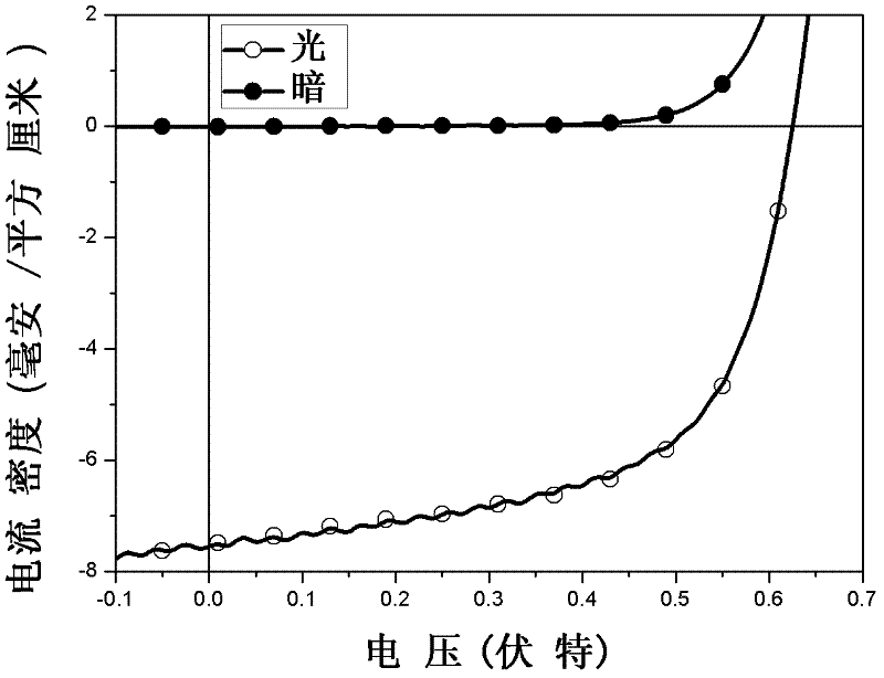
[0037] The transparent conductive glass sputtered with indium tin oxide (ITO) was ultrasonically cleaned with detergent, deionized water, acetone, and isopropanol in sequence, dried with nitrogen, and spin-coated with PEDOT:PSS aqueous solution at 2000 rpm, 150°C Bake for 15 minutes and cool naturally to obtain an anodic finishing layer. Combine 10mg / mL of P088 with PC 70A mixed solution of BM 1:1.3 (mass ratio) (dropped with 3% additive 1-8 diiodooctane) was directly spin-coated on the above-mentioned hole collection layer at a rotational speed of 1500 rpm, as a photoelectric active layer. Then at 4×10 -4 20nm of calcium and 100nm of aluminum were vacuum-deposited under pa as the cathode. image 3 The current-voltage curves of the device without light irradiation and with simulated sunlight irradiation of 100 mW / cm2 are given. The prepared device has an open-circuit voltage of 0.630 volts, a short-circuit current...
Embodiment 3
[0039] The transparent conductive glass sputtered with indium tin oxide (ITO) was ultrasonically cleaned with detergent, deionized water, acetone, and isopropanol in sequence, dried with nitrogen, and spin-coated with PEDOT:PSS aqueous solution at 2000 rpm, 150 ° C Bake for 15 minutes and cool naturally to obtain an anodic finishing layer. Then 12mg / mL P088 solution was spin-coated on it at 4000rpm, baked at 150°C for 10min, then irradiated with ultraviolet light for 2min, and then 10mg / mL of P088 was mixed with PC 60 A mixed solution of BM 1:1.3 (mass ratio) (with 3% additive 1-8 diiodooctane added dropwise) was spin-coated thereon at a rotational speed of 1500 rpm, as a photoelectric active layer. Then at 4×10 -4 20nm of calcium and 100nm of aluminum were vacuum-evaporated under Pa as the cathode. Figure 4 The current-voltage curves of the device without light irradiation and with simulated sunlight irradiation of 100 mW / cm2 are given. The prepared device has an open cir...
PUM
 Abstract
Description
Claims
Application Information