Method for recovering silicon powder from monocrystalline and polycrystalline silicon cutting wastes by utilizing potential adjustment centrifugal process

A technology for cutting waste and potential regulation, which is applied in the direction of chemical instruments and methods, silicon carbide, silicon compounds, etc., can solve the problems of difficult reduction principle, long process flow, complicated operation, etc., and achieves short separation operation time, simple process flow, The effect of process parameter stabilization

Inactive Publication Date: 2012-09-12
UNIV OF SCI & TECH BEIJING
View PDF6 Cites 14 Cited by
  • Summary
  • Abstract
  • Description
  • Claims
  • Application Information

AI Technical Summary

Problems solved by technology

[0007] A comprehensive evaluation of the technical characteristics of the above separation and recovery of silicon shows that the process flow is generally long and the operation is complicated. Some methods even convert silicon from a simple substance into a compound, and it is more difficult to further recover the principle.
In addition, most separation methods use some

Method used


Image

  • Method for recovering silicon powder from monocrystalline and polycrystalline silicon cutting wastes by utilizing potential adjustment centrifugal process
  • Method for recovering silicon powder from monocrystalline and polycrystalline silicon cutting wastes by utilizing potential adjustment centrifugal process
  • Method for recovering silicon powder from monocrystalline and polycrystalline silicon cutting wastes by utilizing potential adjustment centrifugal process

Examples


specific Embodiment 1

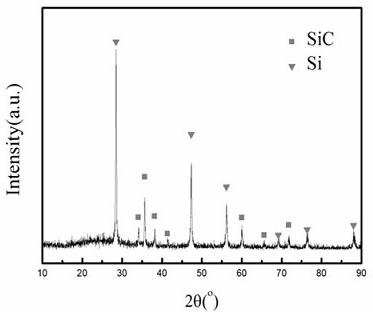
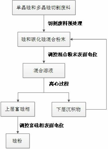
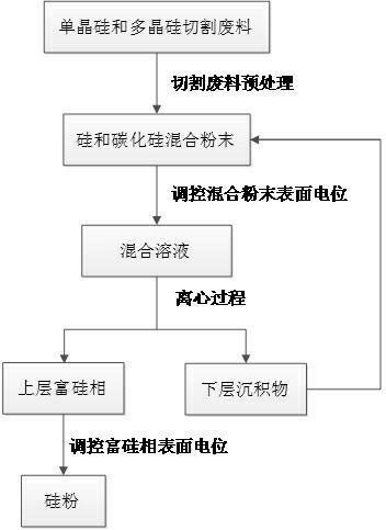
[0033] Add water to the mixed powder with polyethylene glycol removed according to the liquid-solid ratio of 4:1, adjust the pH value to 7 with sodium hydroxide solution, put the mixed solution into a centrifuge, centrifuge for 10 minutes, and rotate at 5000 rpm / min, the number of centrifugation is 3 times, the upper layer liquid is taken out and the pH value is adjusted to 2, the silicon powder settles rapidly, dried and recovered; the lower layer liquid is returned to the original mixed powder solution. It can be seen from the XRD pattern that only a small amount of silicon carbide is contained in the recovered silicon powder.

specific Embodiment 2

[0034] Add water to the mixed powder with polyethylene glycol removed according to the liquid-solid ratio of 10:1, adjust the pH value to 8 with sodium hydroxide solution, put the mixed solution into a centrifuge, centrifuge for 20 minutes, and rotate at 3000 rpm / min, the number of centrifugation is 5 times. Take out the upper layer liquid and adjust the pH value to 2, the silicon powder will settle rapidly, dry and recover; the lower layer liquid will return to the original mixed powder solution. Its XRD result is identical with embodiment one.

specific Embodiment 3

[0035] Add water to the mixed powder with polyethylene glycol removed according to the liquid-solid ratio of 5:1, adjust the pH value to 9 with sodium hydroxide solution, put the mixed solution into a centrifuge, centrifuge for 15 minutes, and rotate at 4000 rpm / min, the number of centrifuges is 4 times. Take out the upper layer liquid and adjust the pH value to 2, the silicon powder will settle rapidly, dry and recover; the lower layer liquid will return to the original mixed powder solution. Its XRD result is identical with embodiment one.


PUM


Abstract

The invention discloses a method for recovering a silicon powder from monocrystalline and polycrystalline silicon cutting wastes by utilizing a potential adjustment centrifugal process. The method comprises the following steps of: firstly, performing pretreatment on the cutting wastes to remove a polyethylene glycol solution; drying to obtain a mixed powder of silicon and silicon carbide; adding water to the mixed powder and stirring; regulating a pH value to 6-9 by acid and base; performing centrifugal separation for a plurality of times, and then, adding the acid to an isolated upper layer suspension to regulate the pH value to 1-3 so as to enable a silicon powder aggregate to grow up; and performing standing settling for 30min or centrifugal settling for 5min to collect the silicon powder, wherein the purity of the silicon powder can reach more than 80 percent.

Description

[0001] technical field [0002] The invention relates to a method for recovering silicon powder in monocrystalline silicon and polycrystalline silicon wire cutting waste. [0003] Background technique [0004] The utilization of solar energy has become an important direction of new energy development. The research and development of various solar photovoltaic cells is in full swing, and more than 80% of solar cells are made of high-purity polysilicon as the basic raw material. At present, various photovoltaic cells The product occupies an absolute dominant position. Generally, when making silicon wafers for solar cells, high-purity crystalline silicon must first be cast into ingots and then sliced. During the slicing process, the part accounting for more than 30% of the weight of the silicon ingot will be multi-wire cut into fine-sized silicon powder waste, which is used as a cutting abrasive silicon carbide powder, metal shavings generated by grinding, and as a cutting ab...

Claims


Application Information

Patent Timeline
IPC IPC(8): C01B33/037C01B31/36C01B32/956
Inventor 朱鸿民刘苏宁黄凯
Owner UNIV OF SCI & TECH BEIJING
Why Eureka
Try Eureka