Gas heat carrier low-temperature pyrolyzing furnace and gas heat carrier low-temperature pyrolyzing method

A gas heat carrier and low-temperature pyrolysis technology, which is used in the field of low-temperature tar, gas and semi-coke, can solve the problems of large energy consumption and increase the processing burden of the gas cooling system, so as to reduce dust content, reduce sewage treatment capacity, and reduce losses. Effect

Inactive Publication Date: 2012-09-19
北京德天御投资管理有限责任公司
View PDF6 Cites 27 Cited by
  • Summary
  • Abstract
  • Description
  • Claims
  • Application Information

AI Technical Summary

Problems solved by technology

[0004] The purpose of the present invention is to solve the technical problems caused by the use of high-moisture raw materials that consume a lot of energy and increase the processing burden of the subseq

Method used


Image

  • Gas heat carrier low-temperature pyrolyzing furnace and gas heat carrier low-temperature pyrolyzing method
  • Gas heat carrier low-temperature pyrolyzing furnace and gas heat carrier low-temperature pyrolyzing method
  • Gas heat carrier low-temperature pyrolyzing furnace and gas heat carrier low-temperature pyrolyzing method

Examples


Embodiment 1

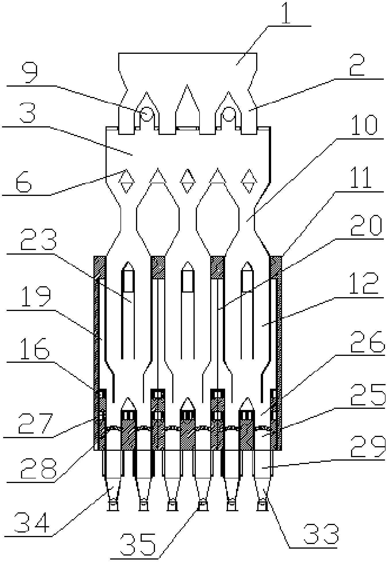
[0036] Embodiment 1: as figure 1 , figure 2 and image 3 As shown, a gas heat carrier low-temperature pyrolysis furnace for high-moisture non-viscous or weak-viscosity solid fuels includes a furnace body 11, a furnace top bunker 1, a furnace top distributor 2, a raw material drying section 3, Gas separation section 10, pyrolysis section 12, combined coke quenching section 25, semi-coke exporting device 33.

[0037] The raw material drying section 3 includes a main dry gas pipeline 4 , a dry gas branch pipe 5 , an air distribution umbrella 6 , a gas distribution bottom plate 7 , a dry gas outlet pipe 9 , and a gas barrier pipe 10 . The drying section adopts a steel structure; the drying air distribution air array umbrella adopts a triangular structure, and may also adopt a circular structure.

[0038] The pyrolysis section 12 includes a gas pipeline 13, an air pipeline 14, a gas-air mixed burner 15, a combustion chamber 16, a combustion chamber distribution flower wall 17, ...

Embodiment 2

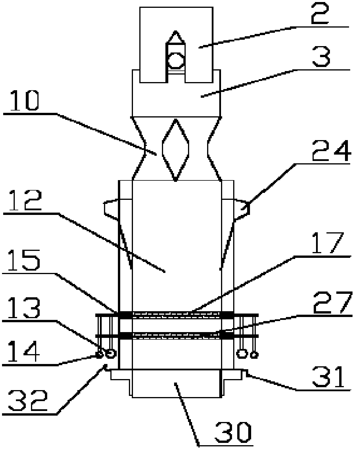
[0042] Embodiment 2: as Figure 4 , Figure 5 As shown, this embodiment is a form of drying gas distribution structure of the basic structural unit drying section 3, and the described drying gas distribution structure adopts a steel structure. The drying gas distribution structure is located at the bottom of the drying section, and at the top of the gas barrier area between the drying section and the pyrolysis section. The hot gas is evenly distributed into the air distribution umbrella 6 from the dry gas main pipeline 4 through the dry gas branch pipe 5. The cut surface of the air distribution umbrella is in the form of a triangle. There is a gap, and the dry gas enters the furnace from the bottom gap space.

Embodiment 3

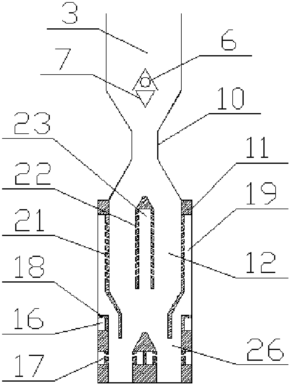
[0043] Embodiment 3: as Image 6 , Figure 7 As shown, this embodiment is a form of drying gas distribution structure of the basic structural unit drying section 3, and the described drying gas distribution structure adopts a steel structure. The dry gas distribution structure is located in the middle and upper part of the gas barrier area between the drying section and the pyrolysis section. The hot gas is evenly distributed into the air distribution umbrella 6 from the dry gas main pipeline 4 through the dry gas branch pipe 5. The cut surface of the air distribution umbrella is a fan-shaped structure. The bottom of the air distribution umbrella is open, and the dry gas enters the furnace through the open space at the bottom. .


PUM


Abstract

The invention discloses a gas heat carrier low-temperature pyrolyzing furnace and a gas heat carrier low-temperature pyrolyzing method. High-moisture materials are subjected to drying preprocessing in the pyrolyzing furnace by means of a gas heat carrier convection drying method, and hot gas is uniformly distributed in a drying section under the action of a gas distribution umbrella. Dried materials enter a dry distillation area where gas heat carriers transversely penetrate through materials, and exchange heat with the gas heat carriers prior to heating to enable low-temperature pyrolytic reaction. Gas in the furnace is formed by mixing lower coke quenching coal gas with hot flue gas in a combustion area, enters a flame path, then flows across a material layer from a flame path lattice wall to a gas collection lattice wall to enter a gas collection chamber, and is finally led out of the furnace through a gas collection passage formed by double-faced gas collection lattice walls and gas collection chamber gas distribution bricks. Pyrolyzed product hot semi-cokes enter a combined dry quenching device to be cooled and pass through a coal gas quenching area and a water-cooling heat exchange area sequentially. A guide chute on the lower portion of the furnace is connected with a discharger and a conveyor, and semi-cokes are uniformly led out and conveyed to a semi-coke storage yard under the action of the discharger and the conveyor.

Description

technical field [0001] The invention relates to a gas heat carrier low-temperature pyrolysis furnace and a gas heat carrier low-temperature pyrolysis method for high-moisture non-viscous or weakly viscous solid fuels, mainly used for treating non-viscous or weakly viscous solid fuels with a particle size of less than 120mm Solid fuels (such as lignite, long-flame coal, gas coal, etc.), produce low-temperature tar, gas and semi-coke through low-temperature pyrolysis reactions. Background technique [0002] At present, the conventional gas heat carrier low-temperature dry distillation process requires the use of block raw materials, the particle size of which is required to be within the range of 20-120 mm, and requires high thermal stability and low moisture content. For raw materials with high moisture content, poor thermal stability and small particle size, they need to be dried and pretreated before thermal processing to make briquettes with a certain particle size. [00...

Claims


Application Information

Patent Timeline
IPC IPC(8): C10B49/04C10B39/00C10B57/10
Inventor 范涛
Owner 北京德天御投资管理有限责任公司
Why Eureka
Try Eureka