Preparation method of glass rod surface micro-lens array

A technology of microlens array and glass rod, which is applied to photoengraving process of pattern surface, lens, process for producing decorative surface effect, etc., can solve the problems of fixed structure parameters, high processing cost, low processing efficiency, etc. To achieve the effect of simple preparation process, adjustable size and large adjustment range

Active Publication Date: 2012-10-31
XI AN JIAOTONG UNIV
View PDF6 Cites 16 Cited by
  • Summary
  • Abstract
  • Description
  • Claims
  • Application Information

AI Technical Summary

Problems solved by technology

However, these methods generally have great limitations: expensive processing equipment or special processing materials are required, the processing efficiency is low and the processing process is complicated, so the processing cost is relatively high; in addition, the curved microlens array produced by these processes The precision is not high, the structural parameters are relatively fixed, and cannot be flexibly adjusted

Method used


Image

  • Preparation method of glass rod surface micro-lens array
  • Preparation method of glass rod surface micro-lens array
  • Preparation method of glass rod surface micro-lens array

Examples


Embodiment 1

[0023] This embodiment includes the following steps:

[0024] Step 1, selecting a glass rod with a diameter of 3 mm for preparing a microlens array, the glass rod being K9 glass with a polished surface;

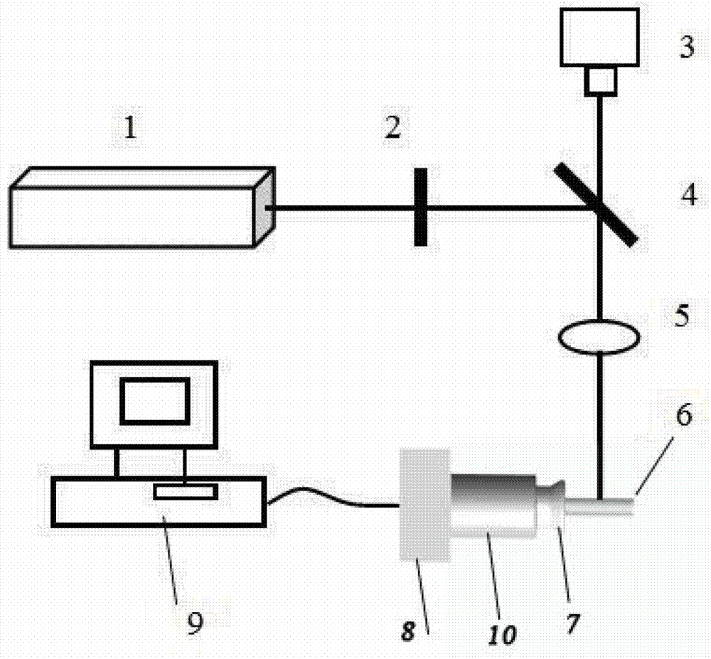
[0025] Step 2, fix the glass rod 6 on the fixture 7, fix the fixture 7 on the rotating shaft 10, and fix the other end of the rotating shaft 10 on the three-dimensional precision displacement platform 8, the computer 9 and the three-dimensional precision displacement platform 8 and the rotating shaft 10 Connected to control the movement of the two, the laser emitted by laser 1, the laser parameters are pulse width 30fs, wavelength 800nm, single pulse energy 3μJ, repetition frequency 1KHz, through the controllable switch 2, mirror 4, and then through The objective lens 5 with a numerical aperture value of 0.7 is focused on the surface of the glass rod 6, and the CCD camera 3 monitors the entire processing process;

[0026] Step 3. According to the processing requirements, con...

Embodiment 2

[0032] Step 1, selecting a glass rod with a diameter of 2 mm for preparing a microlens array, the glass rod being K9 glass with a polished surface;

[0033] Step 2, fix the glass rod 6 on the fixture 7, fix the fixture 7 on the rotating shaft 10, and fix the other end of the rotating shaft 10 on the three-dimensional precision displacement platform 8, the computer 9 and the three-dimensional precision displacement platform 8 and the rotating shaft 10 Connected to control the movement of the two, the laser emitted by laser 1, the laser parameters are pulse width of 80fs, wavelength of 400nm, single pulse energy of 1μJ, repetition frequency of 1KHz, through the controllable switch 2, mirror 4, and then through The objective lens 5 with a numerical aperture value of 0.3 is focused on the surface of the glass rod 6, and the CCD camera 3 monitors the entire processing process;

[0034] Step 3: Control the rotation of the rotating shaft 10 and the movement of the three-dimensional p...

Embodiment 3

[0039] Step 1, selecting a glass rod 6 with a diameter of 10 mm for preparing a microlens array, the glass rod being quartz glass with a polished surface;

[0040] Step 2, fix the glass rod 6 on the fixture 7, fix the fixture 7 on the rotating shaft 10, and fix the other end of the rotating shaft 10 on the three-dimensional precision displacement platform 8, the computer 9 and the three-dimensional precision displacement platform 8 and the rotating shaft 10 Connected to control the movement of the two, the laser emitted by laser 1, the laser parameters are pulse width 30fs, wavelength 800nm, single pulse energy 5μJ, repetition frequency 10KHz, through the controllable switch 2, mirror 4, and then through The objective lens 5 with a numerical aperture value of 0.5 is focused on the surface of the glass rod 6, and the CCD camera 3 monitors the entire processing process;

[0041] Step 3. According to the processing requirements, control the rotation of the rotating shaft 10 and t...


PUM

PropertyMeasurementUnit
diameteraaaaaaaaaa
diameteraaaaaaaaaa
diameteraaaaaaaaaa

Abstract

The invention provides a preparation method of a glass rod surface micro-lens array. The preparation method comprises the steps of placing a glass bar with a micro-lens array to be prepared on a femtosecond processing platform; controlling the femtosecond processing platform to move as processing requirement, and synchronously controlling the irradiation of a single point, and ablating to generate a crater array on the surface of the glass bar; and transferring the glass bar with the ablated crater into a diluted hydrofluoric acid solution, and heating under the ultrasonic water bath for providing assistance, and removing the glass bar from diluted hydrofluoric acid solution, and sequentially washing through acetone, absolute ethyl alcohol and deionized water under an ultrasonic water bath condition, thus obtaining the glass bar with the micro-lens array on the surface. According to the preparation method, the technology of etching under a wet chemical method along with the assistance of femtosecond laser point-by-point irradiation is adopted to prepare a high-quality micro-lens array on the surface of the glass bar.

Description

technical field [0001] The invention relates to the field of femtosecond laser micro-nano processing and preparation of micro-optical devices, in particular to a method for preparing a micro-lens array on the surface of a glass rod. Background technique [0002] The microlens array distributed on the special curved surface not only retains the characteristics of the traditional microlens array: each small lens can focus and image independently, and the size of the clear aperture of each lens is very small (generally several microns to hundreds of Microns), a high degree of integration; and has other special properties. For example, if the microlens array is evenly arranged on the spherical surface, each lens can independently accept light at a certain angle, resulting in a very large viewing angle range, and it has a very large advantage in capturing dynamic targets; in addition, the microlens The lens array is evenly distributed on the surface of the cylinder, which can al...

Claims


Application Information

Patent Timeline
Patent Type & Authority Applications(China)
IPC IPC(8): B81C1/00G02B3/00G03F7/00
Inventor 陈烽杨青邓泽方刘贺炜边浩杜广庆司金海侯洵
Owner XI AN JIAOTONG UNIV
Why Eureka
Try Eureka