Micro-speaker oscillation plate edge material, micro-speaker oscillation plate, micro-speaker, and electronic apparatus

A technology of micro-speaker and vibrating membrane, which is applied in the direction of fixing/tightening of flat vibrating membrane, transducer diaphragm and vibrating membrane, etc. It can solve the problems of high heat resistance, insufficient resistance to multi-bending, damage, cracking, etc. , to achieve the effect of excellent internal friction, excellent vibration resistance and excellent characteristics

Inactive Publication Date: 2012-12-12
AZUMA CHEM
View PDF8 Cites 9 Cited by
  • Summary
  • Abstract
  • Description
  • Claims
  • Application Information

AI Technical Summary

Problems solved by technology

[0022] In addition, although the use of a multi-layered material has been proposed from the conventional single-layer material as described above, in the conventionally proposed structure, the high heat resistance and multi-bending resistance that can support high output are not sufficient. does not fully meet the above requirements
[0023] More specifically, among general-purpose materials such as PAI, PI, and PEI disclosed in various patent documents, it cannot be said that the high heat or strong vibration transmitted from the voice coil accompanying the increase in power and sound quality of the speaker Durability is sufficient, but there are problems such as cracking and damage over time

Method used


Image

  • Micro-speaker oscillation plate edge material, micro-speaker oscillation plate, micro-speaker, and electronic apparatus
  • Micro-speaker oscillation plate edge material, micro-speaker oscillation plate, micro-speaker, and electronic apparatus
  • Micro-speaker oscillation plate edge material, micro-speaker oscillation plate, micro-speaker, and electronic apparatus

Examples


Embodiment 1

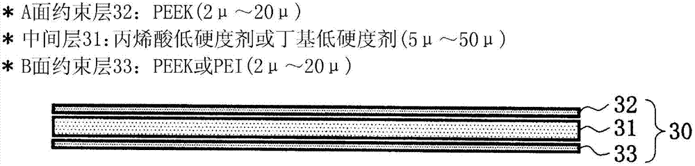
[0051] The diaphragm edge material for a microspeaker of the present invention will be described.

[0052] Such as figure 1 As shown, the diaphragm edge material 30 for a microspeaker of the present invention has a constrained layer (2 μm to 20 μm thick) 32, 33 made of PEEK from an intermediate layer (5 μm thick) made of acrylic low hardness agent or butyl low hardness agent. ~50μm) 31 clamping structure on both sides.

[0053] Figure 9A It is a graph showing the relationship between the thickness of the constraining layers 32 and 33 and the lowest frequency of the microspeaker. The optimum ranges for the thicknesses of the constraining layers 32 and 33 will be described below.

[0054] The horizontal axis of the graph is the lowest value of the output frequency of the microspeaker using the above-mentioned microspeaker diaphragm edge material 30 (hereinafter referred to as the lowest frequency (Hz)), and the vertical axis is the single PEEK used as the constraining layer...

Embodiment 2

[0085] Hereinafter, examples of a microspeaker diaphragm using the microspeaker diaphragm edge material having the above-mentioned excellent characteristics and a microspeaker incorporating the microspeaker diaphragm will be described with reference to the drawings.

[0086] Figure 3A and Figure 3B It is a figure for demonstrating an example of the diaphragm using the diaphragm edge material for microspeakers of this invention.

[0087] exist Figure 3A Among them, the reference numeral 20 is a high elastic material (paper, engineering plastic film or light metal sheet such as aluminum, magnesium), and the reference numeral 30 is a micro Loudspeaker diaphragm edge material.

[0088] The microspeaker diaphragm edge material 30 in this embodiment has a ring shape, and is integrally molded after being aligned so that its outer peripheral portion overlaps with the inner peripheral portion of the high elastic material 20 .

[0089] The high elastic material 20 and the diaphra...


PUM


Abstract

To provide a micro-speaker oscillation plate edge material, an oscillation plate employing the micro-speaker oscillation plate edge material, a micro-speaker, and an electronic apparatus, whereby such characteristics as heat resistance, cold resistance, moisture resistance, moldability, and high internal loss are improved, polyether etherketone (PEEK) is disposed on one face of an intermediate layer having a high damping effect, and either polyether etherketone (PEEK) or polyetherimide (PEI) is disposed on the other face thereof, as binding layers.

Description

technical field [0001] The present invention relates to a vibrating membrane edge material technology for micro-speakers used in electro-acoustic converters of electronic equipment such as mobile phones, portable audio equipment, and notebook computers, and particularly relates to heat resistance, cold resistance, moisture resistance, and formability Microspeaker diaphragm edge material excellent in high internal friction, etc., a microspeaker diaphragm using the microspeaker diaphragm edge material, a microspeaker, a cellular phone, a portable audio device, a notebook computer, etc. using the microspeaker Electronic equipment. Background technique [0002] Currently, polyimide (PI: Polyimide), polyamide- Imide (PAI: Polyamide Imide), polyphenylene sulfide (PPS: Ploy Phenylene Sulfide Resin), polyetherimide (PEI: Polyetherimide), polyethylene naphthalate (PEN: Polyethylene naphthalate), poly A diaphragm of a single structure obtained by heating and stamping engineering pla...

Claims


Application Information

Patent Timeline
Patent Type & Authority Applications(China)
IPC IPC(8): H04R7/06H04R9/02H04R9/06
CPCH04R9/02H04R7/06H04R9/06H04R7/125H04R7/18H04R1/00
Inventor 山田精吾
Owner AZUMA CHEM
Why Eureka
Try Eureka