Method and device for demodulating fiber bragg grating (FBG) sensor

A demodulation method and sensor technology, which are applied in the direction of using optical devices to transmit sensing components, etc., can solve the problems of high precision of comb filters, reduced measurement accuracy of demodulators, complicated manufacturing process, etc., and improve spectral shape customization. Ability, reduce the difficulty of production, and the effect of reliable craftsmanship

Active Publication Date: 2015-03-11
杭州联光电子有限公司
View PDF3 Cites 0 Cited by
  • Summary
  • Abstract
  • Description
  • Claims
  • Application Information

AI Technical Summary

Problems solved by technology

However, the comb filter of the F-P interferometer has a high degree of precision and the manufacturing process is relatively complicated. It also needs to use a constant temperature circuit to keep it at a constant temperature, otherwise it will seriously reduce the measurement accuracy of the demodulator when it is used as a wavelength reference device.

Method used


Image

  • Method and device for demodulating fiber bragg grating (FBG) sensor
  • Method and device for demodulating fiber bragg grating (FBG) sensor
  • Method and device for demodulating fiber bragg grating (FBG) sensor

Examples


Embodiment 1

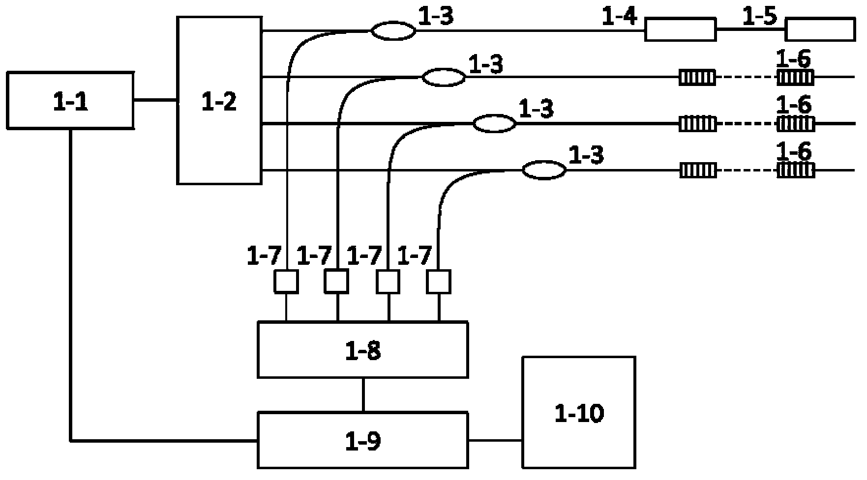
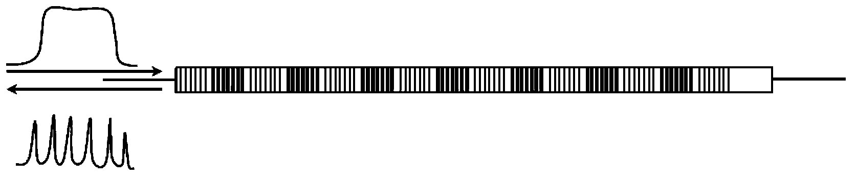
[0033] Example 1. Such as figure 1 As shown, it is a schematic structural diagram of the demodulation device of the FBG sensor based on the reflective FBG comb filter proposed by the present invention, including a wavelength scanning laser 1-1, a 1×N power beam splitter 1-2, and N paths 50:50 Fiber coupler 1-3, reflective FBG comb filter with temperature compensation package 1-4, reference FBG 1-5, FBG sensor 1-6 on (N-1) sensing channels, N photodetection Device (PD) 1-7, amplifier 1-8, data acquisition card 1-9, and computer 1-10. The main characteristics of each device and the working principle of the demodulation device of the FBG sensor are as follows:

[0034] The wavelength-scanning laser 1-1 is a fiber laser, which adopts a ring cavity structure to generate narrowband laser signals. Preferably, the gain device of the fiber laser is an erbium-doped fiber amplifier (EDFA) or a semiconductor optical amplifier (SOA), the wavelength scanning device is an F-P tunable fil...

Embodiment 2

[0044] Example 2. Such as Figure 5 As shown, it is a schematic structural diagram of the demodulation device of the FBG sensor based on the transmissive LPG comb filter proposed by the present invention, including a wavelength scanning laser 5-1, a 1×N power beam splitter 5-2, (N-1) 50:50 fiber optic coupler 5-3, transmissive LPG comb filter 5-4, reference FBG with temperature compensation package 5-5, FBG sensor on (N-2) sensing channel 5-6, N-way photoelectric detectors (PD) 5-7, data acquisition card 5-8, amplifier 5-9 and computer 5-10. The main characteristics of each device and the working principle of the demodulation device of the FBG sensor are as follows:

[0045] The wavelength-scanning laser 5-1 is a fiber laser, which adopts a ring cavity structure and generates narrow-band laser signals. Preferably, the gain device of the fiber laser is an erbium-doped fiber amplifier (EDFA) or a semiconductor optical amplifier (SOA), the wavelength scanning device is an F-P ...

Embodiment 3

[0053] Example 3. Such as Figure 8 As shown, it is a schematic structural diagram of the demodulation device of the FBG sensor based on the serial FBG comb filter proposed by the present invention, including a wavelength scanning laser 8-1, a 1×N power beam splitter 8-2, and N paths 50:50 Fiber coupler 8-3, serial FBG comb filter 8-4, reference FBG with temperature compensation package 8-5, FBG sensor 8-6 on (N-1) sensing channel, N photodetection Device (PD) 8-7, data acquisition card 8-8, amplifier 8-9 and computer 8-10. The main device features and working principles of the demodulation device of the FBG sensor of the serial FBG comb filter are the same as those of the demodulation device of the FBG sensor of the reflective FBG comb filter in Embodiment 1. The main difference is that the serial FBG comb filter 8-4 is formed by the series extension of two or more reflective FBG comb filters 1-4 to make up for the larger wavelength required by the demodulation device of th...


PUM


Abstract

The invention discloses a method and a device for demodulating a fiber bragg grating (FBG) sensor. The method comprises the following steps of: controlling a wavelength scanning laser device to generate narrow-band scanning laser rays with continuously changed wavelengths by using a computer; splitting beams of the narrow-band scanning laser rays generated by the wavelength scanning laser device; enabling a generated reflection spectrum to enter a photoelectric detector again via an optical fiber coupler to be converted into electric signals after the beam-split narrow-band scanning laser rays respectively enter the FBG sensor to be measured and a reflecting FBG comb filter with a temperature compensation package function via the optical fiber coupler, and acquiring the electric signals by the computer after the electric signals are amplified; obtaining wavelengths of peaks of the reflecting FBG comb filter with the temperature compensation package function by the computer through a peak-detection algorithm; calibrating the reflection spectrum of the FBG sensor by the wavelengths; and calculating an absolute wavelength value of the FBG sensor.

Description

technical field [0001] The invention relates to a demodulation method and device of an FBG sensor, belonging to the technical field of optical fiber sensing. Background technique [0002] The fiber grating sensor has high reliability, strong anti-electromagnetic interference ability and corrosion resistance. In particular, its wavelength coding characteristics and the advantages of quasi-distributed measurement on a single fiber are unmatched by other sensors and have broad application prospects. However, one of the most important obstacles restricting the large-scale practical application of FBG sensors is the demodulation of the wavelength signals of FBG sensors. [0003] After more than 20 years of development, a variety of fiber grating demodulation technologies have emerged in the field of fiber grating sensing. Typical demodulation techniques include spectrometer detection method, matched grating demodulation method, unbalanced Mach-Zehnder interferometry, tunable F-...

Claims


Application Information

Patent Timeline
Patent Type & Authority Patents(China)
IPC IPC(8): G01D5/26
Inventor 高少锐张小平柴伊琦
Owner 杭州联光电子有限公司
Why Eureka
Try Eureka