Compact and efficient cold cathode arc source of quasi diffusion arc

A cold cathode, high-efficiency technology, applied in ion implantation plating, metal material coating process, coating, etc., can solve the problems of rate reduction, magnetic field leakage, and unfavorable plasma transmission, so as to improve ion density and ionization rate, promote particle-to-particle collisions, and enhance bombardment effects

Active Publication Date: 2013-02-20
WENZHOU POLYTECHNIC
7 Cites 16 Cited by

AI-Extracted Technical Summary

Problems solved by technology

However, the arc ion plating device of this patent is not designed for a target of a specific size, and the appropriate magnetic field form is not indicated. It is found that not any form of rotating magnetic field can effectively control the arc spot; the invention still relies on dynamic rotation The magnetic field controls the movement of the arc spot, and does not give the core points of realizing the quasi-diffused arc source; this invention does not carry out innovative design on the specific arc source structure, and the rotating magnetic field generating device is ...

Method used

By covering the frequency of the whole target surface and the adjustable dipole rotating radial magnetic field of intensity to control the motion of the arc spot, the radial magnetic field covering the whole target surface makes the arc spot inverse ampere's law move backward along the vertical radial magnetic field direction , while it moves randomly along the direction of the radial magnetic field. Since the radial magnetic field is not limited to a certain range of the target surface, but covers the entire target surface, the random movement of the arc spot along the direction of the radial magnetic field is also along the entire target surface. . At the same time, the high-frequency rotation of the dipole radial magnetic field will make the arc spot also superimpose the rotation movement, so the arc spot will be distributed on the entire target surface under the combined action of a certain magnetic field strength and a certain rotation frequency, greatly reducing the arc spot. spot power density. The rotating radial magnetic field can restrict the plasma in front of the target, restrict the movement of electrons and ions, increase the electron density in front of the target, promote the collision between particles, increase the ion density and ionization rate, and further strengthen the bombardment of ions on the target surface. effect, but the enhancement of the bombardment effect is distributed throughout the target surface, which promotes the thermal field electron emission of the target surface, increases the effective electron quantity, and makes the arc spot concentrated high power density emission (the cause of large particles) It is transformed into thermal field electron emission with uniform low power density on the entire target surface, realizing a quasi-diffusion arc state, greatly reducing particle emission, and improving evaporation and ionization effects at the same time.
The present invention provides the embodiment of multiple magnetic field coupling, and embodiment 2 is the embodiment that the axial magnetic field that traditional target rear end permanent magnet device produces and dipole radially rotating magnetic field coupling, dipole radially rotating magnetic field The axial focus guiding magnetic field in the front section does not participate in the coupling. Figure 9(a)-Figure 9(c) is a schematic diagram of the transient magnetic field distribution of the coupling between the dipole rotating radial magnetic field and the axial magnetic field of the permanent magnet at the rear end of the target in Example 2, and Figure 9(a) is without the target The transient distribution diagram of the dipole rotating radial magnetic field coupled with the end axial magnetic field on the cross section of the target, it can be seen that when other magnetic fields do not work, the dipole radial magnetic field on the target surface is completely parallel to the target surface , forming an acute angle with the edge of the target pointing toward the interior of the target. The high-speed rotation of the two-pole radial rotating magnetic field can make the arc spot uniformly discharge on the entire target surface, reduce the power density, and reduce the emission of large particles. However, if the control is not proper, the moving speed of the arc spot is too fast, and the magnetic field strength and the rotation speed do not match, the arc spot will easily go out of the target to extinguish the arc, and the discharge ...

Abstract

The invention relates to the technical field of preparation of films and coatings, particularly to a compact and efficient cold cathode arc source of a quasi diffusion arc. The cold cathode arc source is composed of an arc source head and a control magnetic field group, wherein the arc source head comprises a target, a target base, a target base shielding cover, a target base plate, an arc striking device and a permanent magnet device; the control magnetic field group comprises a flange sleeve, a flange sleeve insulating bush, a dipolar radial rotating magnetic filed generating device, an axial focusing guiding magnetic field generating device, a coaxial focusing magnetic field magnetic yoke and a flange sleeve shielding cover; and the arc source head is connected with the bottom of the flange sleeve through the target base plate to form a whole arc source structure, and connected with a finance through a flange arranged in front of the flange sleeve. Arc spots are distributed on the whole target surface under the comprehensive action of a certain magnetic field intensity and rotary frequency, the power density of the arc spots is reduced, the quasi diffusion arc state is achieved, launch of large grains is reduced, simultaneously, purified high-density plasmas are extracted through the axial focusing guiding magnetic field, and the transmission efficiency is improved.

Application Domain

Technology Topic

PhysicsSource structure +8

Image

  • Compact and efficient cold cathode arc source of quasi diffusion arc
  • Compact and efficient cold cathode arc source of quasi diffusion arc
  • Compact and efficient cold cathode arc source of quasi diffusion arc

Examples

  • Experimental program(4)

Example Embodiment

[0044] Example 1:
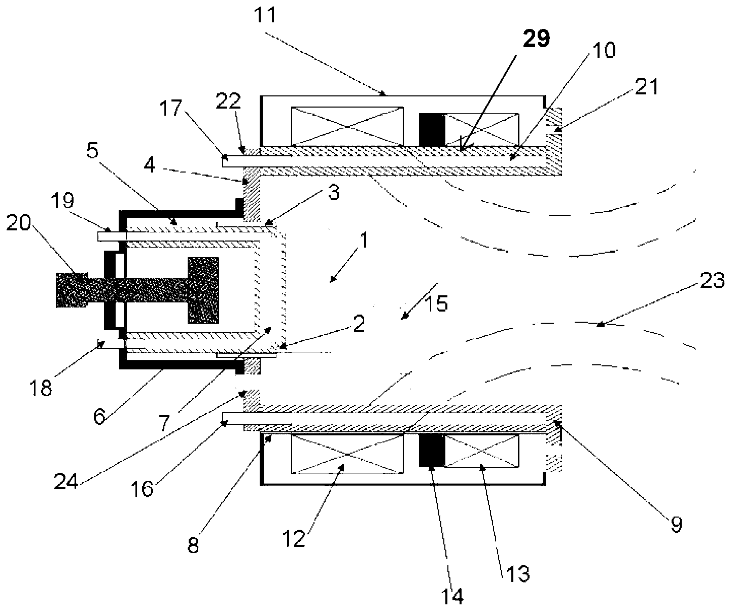
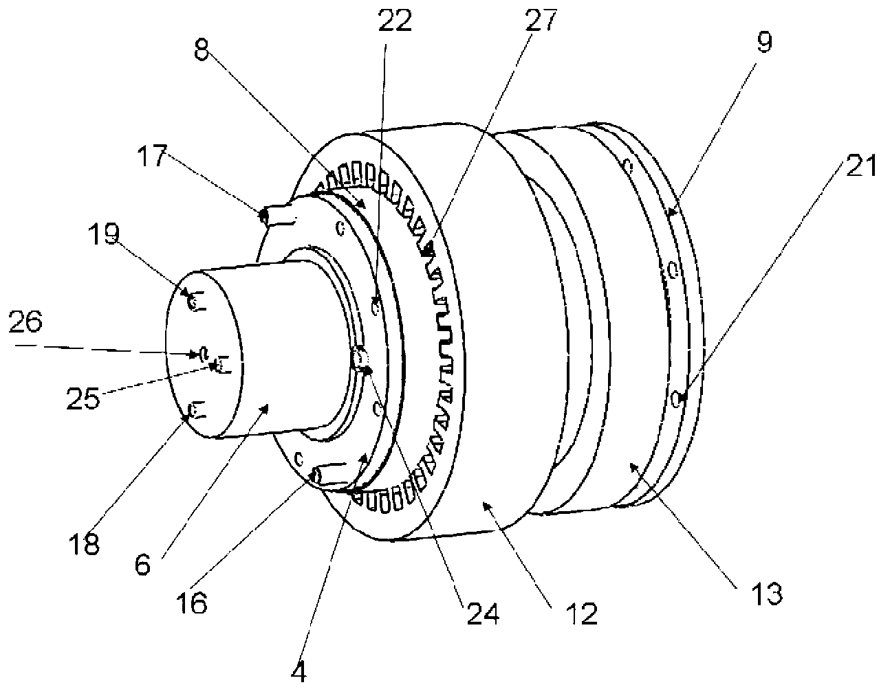
[0045] The invention breaks through the traditional cold cathode arc source magnetic field design ideas, improves the traditional arc source structure, and provides a compact and efficient quasi-diffusion arc cold cathode arc source for circular targets with a diameter of 60-150 mm. figure 1 It is a two-dimensional schematic diagram of the overall structure of a compact and efficient quasi-diffusion arc cold cathode arc source. figure 2 It is a three-dimensional schematic diagram of the overall internal structure of a compact and efficient quasi-diffusion arc cold cathode arc source without a flange sleeve shield. It can be seen from the figure that the compact and efficient quasi-diffusion arc cold cathode arc source is composed of an arc source and a control magnetic field group. The arc source includes target 1, target base 5, target base shield 6, target chassis 4, and lead The arc device 15 and the permanent magnet device 20, the control magnetic field group includes a flange sleeve 29, a flange sleeve insulating sleeve 8, a two-pole radial rotating magnetic field generating device 12, an axial focusing guiding magnetic field generating device 13, and a coaxial focusing magnetic field magnet The yoke 14 and the flange sleeve shielding cover 11, the arc source is connected to the bottom of the flange sleeve 29 through the target chassis 4 to form an integral arc source structure, and the flange 9 at the front of the flange sleeve 29 is connected to the furnace body. The focusing and guiding magnetic field generating device in the control magnetic field group generates focusing magnetic field lines 23.
[0046] The outer side of the flange sleeve 29 is provided with a flange sleeve insulating sleeve 8, and the outer side of the flange sleeve insulating sleeve 8 is provided with a two-pole rotating transverse magnetic field generating device 12, an axial focusing guiding magnetic field generating device 13, and a coaxial focusing magnetic yoke 14. The flange sleeve 29 is provided with a flange sleeve cooling water channel 10, and the bottom of the flange sleeve 29 is provided with a flange sleeve water outlet 17 and a flange sleeve water inlet 16 communicating with the flange sleeve cooling water channel 10. The flange An annular flange 9 is provided at one end of the cooling water channel 10, and a flange connection hole 21 is opened on the edge of the flange 9.
[0047] The target 1 is installed on the target base 5 through the connecting thread 2. The two-pole radial rotating magnetic field generating device 12 and the axial focusing and guiding magnetic field generating device 13 are enclosed outside the flange sleeve 29 and placed coaxially with the target 1 , And the flange sleeve 29 are protected by the flange sleeve insulating sleeve 8; the two-pole radial rotating magnetic field generator 12 is placed around the target material 1, its center is slightly higher than the surface of the target material 1, and the position can be moved; axial focus The guiding magnetic field generating device 13 is placed at the front end of the two-pole radial rotating magnetic field generating device 12, and the coaxial focusing magnetic field yoke 14 is installed at the bottom. A rotating magnetic field generating device slot 27 is opened inside the two-pole radial rotating magnetic field generating device 12; A flange sleeve shielding cover 11 is provided on the periphery of the flange sleeve 29, and the internal magnetic field generating device is protected by the flange sleeve shielding cover 11. The target base chassis 4 is nested outside the target base 5, sealed and protected by the target base insulating sleeve 3, the permanent magnet device 20 is installed in the hollow position inside the target base 5, and is installed with the bottom of the target base 5 through the permanent magnet device The holes 26 are screwed together, and a target base shield 6 is provided on the periphery of the target base 5, and the target base shield 6 protects the inside. The target base 5 is provided with a target base cooling water channel 7, and the target base cooling water channel 7 communicates with the target base water inlet 19 and the target base water outlet 18 respectively. The target base chassis 4 opens an arc starting device installation hole 24 at a position close to the target base 5. The arc starting device 15 is arranged in the arc starting device installation hole 24. One end of the arc starting device 15 corresponds to the target 1. The target base chassis 4 is provided with a target base chassis connecting hole 22 around the target base chassis 4, and the target base chassis 4 is connected to a flange sleeve 29 through the target base chassis connecting hole 22.
[0048] image 3 It is a top view of the position structure between the compact and efficient quasi-diffusion arc cold cathode arc source two-pole radial rotating magnetic field generator, the arc source and the flange sleeve. The two-pole radial rotating magnetic field generating device 12 of the first embodiment of the present invention is composed of a multi-pole (12n, n is an integer, n≥2) iron core skeleton and enameled wire windings. The two-pole radial rotating magnetic field generating device 12 has slots inside. The gap 27, one end of the arc ignition device 15 corresponds to the target 1. The iron core is made of laminated ring-shaped silicon steel sheets with a high magnetic permeability (2000~6000H/m) and a thickness of 00.5mm. The inner circle of the iron core is provided with slots for inserting winding coils. The slot shape is semi-closed. The inner diameter of the iron core is 182mm, which is slightly larger than the outer diameter of the flange sleeve 29. The outer diameter of the iron core is selected according to the standard and is sheathed on the flange sleeve 29 by an insulating sleeve; the surface of the silicon steel sheet is coated with high-voltage insulating paint, iron The core material is cold-rolled silicon steel. The enameled wire winding coil of the two-pole radial rotating magnetic field generating device 12 is made of high-strength polyurethane enameled copper wire (QZY-2), and a two-speed winding with a regular distribution of double pole ratio and a △/2Y connection method is adopted. Each phase consists of 2 six-groups, 2 poles 60 phases with saliency wiring, the polarity between the two phases is opposite; half of the coil groups are reversed to obtain a 120-phase 4-pole winding, that is, all coil poles at 4 poles The same sex, and use a △-shaped connection. There are 6 winding lead wires, the end wires 2U, 2V, and 2W of the three-phase intermediate tap are left unconnected, and the power supply enters from 4U, 4V, and 4W to generate a two-pole radial magnetic field. Figure 4 (a) is a schematic diagram of the three-dimensional structure and cable distribution of the magnetic field generator. Figure 4 (b) is a schematic diagram of the transient magnetic field distribution in the cross-section of the two-pole radial rotating magnetic field. It can be seen that the magnetic field on the cross-section in the middle of the two-pole radial magnetic field generating device 12 is a two-pole radial magnetic field that completely covers the entire target surface. The intensity is uniform, and the frequency and intensity are adjustable.
[0049] The enameled wire winding of the two-pole radial rotating magnetic field generator 12 is excited by a three-phase variable frequency sinusoidal AC power supply with a phase difference of 120°. The current frequency and voltage can be adjusted separately. The voltage range is 0-380V, and the frequency range is 10-500Hz. The voltage adjusts the intensity of the two-pole radial rotating magnetic field, and the rotation speed of the two-pole radial rotating magnetic field is adjusted by the current frequency; the frequency conversion power supply is made with a microprocessor as the core, manufactured by PWM (pulse width modulation), and designed with an active component IGBT module It adopts digital frequency division, D/A conversion, instantaneous value feedback, sinusoidal pulse width modulation and other technologies to produce, with short circuit, overcurrent, overload, overheating and other protection functions.
[0050] The arc spot movement is controlled by the two-pole rotating radial magnetic field with adjustable frequency and intensity covering the entire target surface. The radial magnetic field covering the entire target surface causes the arc spot to retreat linearly in the direction of the vertical radial magnetic field. The radial magnetic field moves randomly. Since the radial magnetic field is not limited to a certain range of the target surface, but covers the entire target surface, the random movement of the arc spot along the radial magnetic field is also along the entire target surface. At the same time, the high-frequency rotation of the two-pole radial magnetic field will cause the arc spot to superimpose the rotating motion. Therefore, the arc spot will be distributed on the entire target surface under the combined action of a certain magnetic field strength and a certain rotation frequency, which greatly reduces the arc. The power density of the spot. The rotating radial magnetic field can constrain the plasma in front of the target, constrain the movement of electrons and ions, increase the electron density in front of the target greatly, promote collisions between particles, increase ion density and ionization rate, and further strengthen the bombardment of ions on the target surface. Effective, but the enhancement of the bombardment effect is distributed throughout the target surface, which promotes the thermal field electron emission of the target surface, increases the effective electron quantity, and makes the arc spot concentrated high power density emission (the cause of large particles) It transforms into uniform low-power density thermal field electron emission across the entire target surface, realizing a quasi-diffusion arc state, greatly reducing particle emission, and improving evaporation and ionization effects.
[0051] However, the radial magnetic field has the effect of confining the plasma. In order to further improve the transmission efficiency of the plasma, the magnetic field is guided through the axial focus of the front section of the target to extract the purified high-density plasma. The axial focusing and guiding magnetic field generating device 13 is composed of an electromagnetic coil wound by enameled wire. The inside and outside of the electromagnetic coil are insulated and protected. The focusing and guiding magnetic field coil is insulated and protected by the flange sleeve insulating sleeve 8 and the flange sleeve 29, and is placed in the second pole diameter. To the front section of the rotating magnetic field generator 12, a ring-shaped high-permeability (2000~6000H/m) iron core coaxial focusing magnetic field yoke 14 can be connected to the bottom to avoid the influence of the axial focusing magnetic field on the rotating radial magnetic field. Direct current is applied to the coil in the focusing and guiding magnetic field generating device 13, and the intensity of the focusing and guiding magnetic field is adjusted by the current.
[0052] Image 6 It is a three-dimensional cross-sectional view of the overall internal structure of the compact and efficient quasi-diffusion arc cold cathode arc source of the embodiment 1 without a flange sleeve shield. The flange sleeve 29 is made of non-magnetic stainless steel. The flange sleeve 29 has a hollow structure and is protected by cooling water. The two-pole radial rotating magnetic field generator 12, the flange sleeve 29 and the target 1 are coaxial with each other. The position of the two-pole radial rotating magnetic field generator 12 on the flange sleeve 29 is adjustable. The cross-section of the flange sleeve 29 is L-shaped. The cooling water passage 10 of the middle flange sleeve is composed of a double-layer stainless steel tube coaxial enclosure. The upper part of the cooling water passage 10 of the flange sleeve is welded with an annular flange 9 and the flange 9 The inner diameter is flush with the inner diameter of the flange sleeve 29, the outer diameter of the flange 9 is flush with the outer diameter of the furnace body flange, the flange 9 has 6-8 flange connection holes 21 through the flange connection holes 21 Connect the flange sleeve 29 to the furnace body as a whole; the lower part of the flange sleeve cooling water channel 10 is connected with a thicker stainless steel flange ring, the inner and outer diameter of the flange ring is the same as the flange sleeve 29, and the bottom of the flange ring has 8 threads Holes, of which two symmetrical threads are through holes, which are used as water inlets and outlets, and the other 6 are used as arc source connection holes.
[0053] There are 8 target base chassis connecting holes 22 on the periphery of the target base chassis 4, corresponding to the 8 threaded holes at the bottom of the flange ring, and 6 of the connecting holes connect the arc source to the bottom of the flange sleeve 29 in the control magnetic field group ; The other two connecting holes correspond to the water inlet 16 of the flange sleeve and the water outlet 17 of the flange sleeve. The target base chassis 4 has a position close to the target base 5 to open an arc starting device installation hole 24.
[0054] Figure 5 It is a three-dimensional cross-sectional view of the arc source of the compact and efficient quasi-diffused arc cold cathode arc source in Example 1. Figures 8(a)-(b) are the compact and efficient quasi-diffused arc cold cathode arc source target base and target of Example 1. It can be seen from the three-dimensional structure diagram of the material that the target base 5 is a non-magnetic double-layer stainless steel cylinder (inner cylinder 30, outer cylinder 31) coaxially enclosing a hollow cylindrical structure, and the upper part of the inner cylinder 30 is closed The inner space of the inner cylinder 30 is the installation position of the permanent magnet device 20, the upper part of the outer cylinder 31 is a stepped closed disc, the height of the step is the same as the height of the connecting thread of the target 1, the outer ring of the step has a connecting thread 2, and the target It is connected to the target base 5 through a stepped thread. The outer diameter of the upper disc of the step is the same as the inner diameter of the bottom thread of the target material 1, the outer diameter of the lower part of the step is the same as the target outer diameter, and the inner diameter of the ring is the same as the target bottom thread inner diameter; the outer diameter of the outer cylinder 31 is the same as the target outer diameter , The outer cylinder 31 has a target base sealing ring groove 28, which is assembled with the target chassis through an insulating sleeve; the outer cylinder 31 and the inner cylinder 30 form a target base cooling water channel 7, and the upper part of the inner cylinder 30 and the upper part of the outer cylinder 31 Leave a certain gap to ensure smooth water flow. The bottom of the target base 5 is connected to a thicker stainless steel flange ring. The inner and outer diameters of the flange ring are the same as the target base. There are two through holes at the bottom of the flange ring symmetrically, which serve as the target base water inlet 19 and the target base outlet. Nozzle 18; a terminal is welded to the bottom of the flange ring as a cathode power connector 25. Figure 7 It is a three-dimensional effect drawing of the arc source of the compact and efficient quasi-diffusion arc cold cathode arc source in Example 1. It can be seen that the target base shield 6 is a stainless steel cylinder coated with insulating paint, and the upper end of the cylinder is welded with a ring method The flange plate is used to install the target base shield 6 on the target chassis 4; the bottom of the cylinder of the target base shield 6 and the target base water inlet 19 and the target base water outlet of the target base 5 There are three holes in the corresponding positions of 18 and the power connector. There is a thicker disc in the middle of the bottom of the cylinder of the target base shield 6 and a threaded hole in the middle of the disc: the permanent magnet device mounting hole 26, the permanent magnet device 20 is threaded through the connecting rod It is connected with the threaded hole and can be adjusted in and out through the screw of the nut to adjust the intensity of the magnetic field. The permanent magnet device 20 is composed of a permanent magnet and a connecting rod as a nut. The permanent magnet is connected with the nut through the connecting rod. The permanent magnet is composed of a single disc-shaped neodymium iron boron magnet. The permanent magnet device 20 is placed in the intermediate space of the target base 5 at the rear end of the target 1 to avoid the influence of cooling water demagnetization. The arc starting device 15 adopts a pneumatic mechanical arc starting or high-frequency arc starting device, and is installed through the arc starting device installation hole 24 on the target base chassis 4.
[0055] This embodiment 1 has a compact structure, high plasma transmission efficiency, can basically realize a quasi-diffused arc state, greatly improves the arc spot discharge form and working stability, improves target etching uniformity and target utilization, and reduces target size The emission of particles improves the transmission efficiency of plasma, and at the same time facilitates the design of the whole machine, is suitable for promotion, and promotes the development of tool coating and decorative coating.

Example Embodiment

[0056] Example 2:
[0057] The present invention provides a variety of magnetic field coupling implementations. Example 2 is an implementation of coupling the axial magnetic field generated by the permanent magnet device at the rear end of the traditional target material and the two-pole radial rotating magnetic field. The magnetic field guided to focus does not participate in the coupling. Picture 9 (a)- Picture 9 (c) is a schematic diagram of the transient magnetic field distribution of embodiment 2 when the two-pole rotating radial magnetic field is coupled with the axial magnetic field of the permanent magnet at the rear end of the target. Picture 9 (a) is the transient distribution diagram of the two-pole rotating radial magnetic field on the cross section of the target without the axial magnetic field coupling at the rear end of the target. It can be seen that when other magnetic fields do not work, the two poles on the target surface The radial magnetic field is completely parallel to the target surface and forms an acute angle pointing to the inside of the target with the edge of the target. The high-speed rotation of the two-pole radial rotating magnetic field can make the arc spot uniformly discharge on the entire target surface, reduce the power density, and reduce the emission of large particles. However, if the control is improper, the arc spot moves too fast, and the magnetic field intensity does not match the rotation speed, the arc spot will easily run outside the target to extinguish the arc, and the discharge will be very unstable. In order to improve the discharge stability, this embodiment 2 adopts the traditional axial magnetic field at the back end of the target material to restrain the arc spot movement for magnetic field coupling. Picture 9 (b) is the transient distribution diagram of the two-pole rotating radial magnetic field on the cross section of the target material coupled with the axial magnetic field at the rear end of the target material. Picture 9 (c) is coupled with the axial magnetic field at the rear end of the target Picture 9 (b) The transient distribution diagram of the two-pole rotating radial magnetic field on the cross-section of the target with the opposite radial magnetic field. It can be seen that under a certain axial magnetic field strength, the distribution of the two-pole radial rotating magnetic field changes to a certain degree. The magnetic field is no longer a radial magnetic field completely parallel to the target surface, but forms a certain angle with the target material. Sharp-angled magnetic field, the sharp-angled magnetic field forms an acute angle with the entire target surface, instead of two acute-angle directions like the arcuate magnetic field, that is, the target surface forms a rotating two-pole sharp-angled magnetic field. The parallel component of the sharp-angle magnetic field is still the radial component, which makes the arc spot retreat linearly in the direction perpendicular to the radial component. At the same time, under the action of the acute angle rule, the arc spot reverses in a straight line while superimposing the radial component. The direction of the movement trend, and the arc spot in the direction along the radial component is no longer a random movement, but a controllable movement, which improves the controllability and stability of the discharge. At the same time, the high-frequency rotation of the two-pole sharp-angle magnetic field will make the arc spot of controllable motion superimpose the rotating motion, so the arc spot is comprehensively coupled at a certain axial magnetic field strength, a certain rotating dipole radial magnetic field strength and a certain rotation frequency. Under the action, the arc spot will be distributed on the entire target surface, which greatly reduces the power density of the arc spot, realizes the quasi-diffusion arc state, greatly reduces the emission of particles, and the coupled magnetic field improves the discharge stability.
[0058] In the second embodiment, on the basis of the traditional axial control magnetic field, a two-pole radial rotating magnetic field is superimposed, and the formed coupling magnetic field can realize the quasi-diffusion arc state while improving the discharge stability.

Example Embodiment

[0059] Example 3:
[0060] Although the quasi-diffusion arc state can be achieved under the combined effect of a certain rotating dipole radial magnetic field strength and a certain rotating frequency, the radial magnetic field has the effect of confining the plasma. In order to further improve the transmission efficiency of the plasma, embodiment 3 It provides a solution to extract the purified high-density plasma through the axial focusing and guiding magnetic field of the front section of the target. Example 3 is an implementation of coupling the two-pole radial rotating magnetic field with the axial focus guiding magnetic field at the front end without the participation of the axial magnetic field generated by the permanent magnet device at the rear end of the traditional target. There are two cases in this scheme, one is the case without focusing guide yoke, and the other is the case with focusing guide yoke. Picture 10 (a) It is the transient distribution diagram of the two-pole rotating radial magnetic field pointing to one end of the target material in the cross section of the target material and the coupling magnetic field in the transmission space under a certain axial focusing and guiding magnetic field strength when the non-focus guiding yoke is used; Picture 10 (b) When the non-focusing guiding yoke, under a certain axial focus guiding magnetic field strength, and Picture 10 (a) The transient distribution diagram of the two-pole rotating radial magnetic field with the opposite radial magnetic field in the target cross section and the coupled magnetic field in the transmission space; Picture 10 (c) is the transient distribution diagram of the two-pole rotating radial magnetic field pointing to one end of the target material in the cross section of the target material and the coupling magnetic field in the transmission space under a certain axial focusing and guiding magnetic field strength when there is a focusing guiding yoke; Picture 10 (d) When there is a focus guide yoke, under a certain axial focus guide magnetic field strength, and Picture 10 (c) The transient distribution diagram of the two-pole rotating radial magnetic field in the cross section of the target material and the coupled magnetic field in the transmission space with the opposite radial magnetic field direction; it can be seen that the axial focus guiding magnetic field changes the distribution of the magnetic field in the transmission space. The axial magnetic field strength of the transmission space is improved, that is, a non-equilibrium quasi-diffusion arc coating process can be realized. While reducing the discharge power density and reducing the emission of large particles, it reduces the restriction of the plasma target surface and improves the plasma transmission to the transmission space. Transport efficiency and density, and it is very effective. At the same time, it can be seen that the participation of the axial focus guiding magnetic field changes the state of the two-pole radial magnetic field, that is, a sharp-angle magnetic field that forms a certain acute angle with the target surface similar to Example 2 is formed. At this time, the axial focus guiding magnetic field can greatly affect the dipole radial magnetic field. For relatively large targets, even two sharp angles are formed, which shortens the trajectory of the arc spot's acute-angle drift movement and makes it easy to extinguish the arc. When there is a focus guide yoke, the axial focus guide magnetic field is mostly constrained by the yoke, which has little effect on the two-pole radial magnetic field of the target surface. Basically, it forms a deformation with a small acute angle and only forms An acute angle in one direction is similar to the case of Example 2. In this way, the discharge stability can be improved, the diffusion arc state can be realized, and the plasma transmission efficiency can be improved at the same time. Therefore, the embodiment of this solution provides an arc source solution with high efficiency, stable discharge, and quasi-diffusion arc state.

PUM

no PUM

Description & Claims & Application Information

We can also present the details of the Description, Claims and Application information to help users get a comprehensive understanding of the technical details of the patent, such as background art, summary of invention, brief description of drawings, description of embodiments, and other original content. On the other hand, users can also determine the specific scope of protection of the technology through the list of claims; as well as understand the changes in the life cycle of the technology with the presentation of the patent timeline. Login to view more.

Similar technology patents

Optical modulator

ActiveCN111240048AEfficient modulationFast movementNon-linear opticsElectrically conductiveIr microscope
Owner:GUIZHOU MINZU UNIV

Transportation cabin for packaging pressure testing and emptying equipment

ActiveCN105217176AFast movementIncreased cargo heightLarge containersEngineeringVapor–liquid separator
Owner:PETRO OIL & LUBRICANT RES INST OF THE GENERAL LOGISITIC DEPT OF PLA

Classification and recommendation of technical efficacy words

  • Fast movement
  • Short stay

Train unmanned turning-back method based on CBTC (communication based train control) system

InactiveCN103010271AShort stayCompressed foldback runtimeAutomatic systemsEngineeringWorkload
Owner:TRAFFIC CONTROL TECH CO LTD

Printing and dyeing wastewater autotrophic denitrification denitriding device and method

ActiveCN105621608AFast startupShort stayTreatment with anaerobic digestion processesWaste water treatment from textile industryPyriteElectron donor
Owner:UNIV OF SCI & TECH BEIJING +2
Why Eureka
Try Eureka