Copper oxide doped tin dioxide base ammonia gas sensitive sensor manufacturing method

A tin dioxide-based, gas-sensing sensor technology is applied in the field of preparation of ammonia gas-sensing sensing elements, and can solve the problems of low sensitivity, long response-recovery time, etc., and achieve high sensitivity, short response and recovery time, and film-forming quality. Good results

Inactive Publication Date: 2013-03-20
HEBEI UNIV OF TECH
View PDF0 Cites 13 Cited by
  • Summary
  • Abstract
  • Description
  • Claims
  • Application Information

AI Technical Summary

Problems solved by technology

However, the ammonia sensors currently available in the domestic market have disadvantages such as low sensitivity and long response-recovery time.

Method used


Image

  • Copper oxide doped tin dioxide base ammonia gas sensitive sensor manufacturing method
  • Copper oxide doped tin dioxide base ammonia gas sensitive sensor manufacturing method
  • Copper oxide doped tin dioxide base ammonia gas sensitive sensor manufacturing method

Examples


Embodiment 1

[0027] Preparation of SnO by RF Sputtering 2 Thin film: Al first 2 o 3 The ceramic tubes were cleaned with alcohol and dried before placing them on the sample holder.

[0028] 1. Place the Cu target and the Sn target with a purity of 99.99% on two RF targets respectively. Vacuum the system until the system air pressure is close to 10 -5 Pa.

[0029] 2. After vacuuming, argon and oxygen with an argon-oxygen ratio of 3:1 are introduced into the system.

[0030] 3. Pre-sputter for 10 minutes when starting sputtering. During this process, adjust the power of the Sn target to 80W and the power of the Cu target to 40W. Take out the sample after 45 minutes of sputtering.

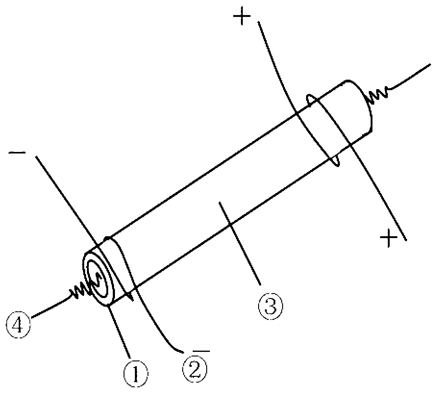
[0031] 4. Sputter with SnO 2 Material Al 2 o 3 The ceramic tubes were annealed at 500 °C for 3 h so that the Al 2 o 3 The SnO required for the surface formation of ceramic tubes 2 film, such as figure 1 As shown, Al 2 o 3 The ceramic tube 1 has a built-in heating wire 4 for heating Al 2 o 3 Ceramic ...

Embodiment 2

[0035] Preparation of SnO by RF Sputtering 2 Thin film: Al first 2 o 3 The ceramic tubes were cleaned with alcohol and dried before placing them on the sample holder.

[0036] 1. Place the Cu target and the Sn target with a purity of 99.99% on two RF targets respectively. Vacuum the system until the system air pressure is close to 10 -5 Pa.

[0037] 2. After vacuuming, argon and oxygen with an argon-oxygen ratio of 4:1 are introduced into the system.

[0038] 3. Pre-sputter for 10 minutes at the start of sputtering. During this process, adjust the power of the Sn target to 60W and the power of the Cu target to 30W. Take out the sample after 45 minutes of sputtering.

[0039] 4. Sputter with SnO 2 Material Al 2 o 3 The ceramic tube was annealed at 300 °C for 2 h to allow the Al 2 o3 The SnO required for the surface formation of ceramic tubes 2 film, such as figure 1 As shown, Al 2 o 3 A heating wire is built into the ceramic tube to heat the Al 2 o 3 Ceramic tube...


PUM


Abstract

The present invention discloses a copper oxide doped tin dioxide base ammonia gas sensitive sensor manufacturing method. The method comprises the following steps: sequentially placing a Cu target material with a purity of 99.99% and a Sn target material with a purity of 99.99% on two radio frequency sputtering targets, and placing a Al2O3 ceramic tube on a sample holder; carrying out vacuum pumping on the system before sputtering until air pressure of the system achieves 10<-3>-10<-5> Pa; opening gas path valves of oxygen gas and argon gas, wherein the air pressure is maintained to 6*10<0>-3*10<-1> Pa; carrying out pre-sputtering for 10 min, then removing a blocking disc, concurrently adjusting a power of the Sn target to 60-80 W, adjusting a power of the Cu target to 20-60 W, and sputtering for 45 min; opening the vacuum chamber to take the sample when the air pressure is 10<5> Pa; and carrying out annealing for 1-3 h at a temperature of 300-500 DEG C in a muffle furnace to obtain the finished product. The manufactured gas sensitive element provides good selectivity for ammonia gas, can quickly and effectively detect ammonia gas from a lot of mixing gas, and has characteristics of high sensitivity and short response recovery time.

Description

technical field [0001] The invention belongs to a gas sensing element, in particular to a copper oxide (CuO) doped tin dioxide (SnO 2 ) is a method for preparing a thin film type highly selective ammonia gas sensing element. technical background [0002] Ammonia is a poisonous, colorless, irritating and foul-smelling gas that is widely used in industry. It has irritating and corrosive effects on the upper respiratory tract of animals or humans, and is often adsorbed on the skin, mucous membranes and conjunctiva, resulting in Irritation and inflammation, which can be life-threatening in severe cases. At present, the gas sensor for detecting ammonia has been widely used in municipal, fire protection, gas, telecommunications, petroleum, chemical, coal, electric power, pharmaceutical, metallurgy, coking, storage and transportation and other industries. The main parameters of the ammonia sensor are sensitivity, response-recovery time and selectivity. [0003] Metal-semiconduct...

Claims


Application Information

Patent Timeline
Patent Type & Authority Applications(China)
IPC IPC(8): C23C14/35C23C14/08G01N27/22
Inventor 潘国峰何平韩永张炳强夏克文
Owner HEBEI UNIV OF TECH
Why Eureka
Try Eureka