Dry method selective non-catalytic reduction method and device

A selective, non-catalytic technology, applied in chemical instruments and methods, separation methods, dispersed particle separation, etc., can solve the problems of energy waste, water wall corrosion, increase in fly ash carbon content, etc., and achieve simple, reliable and economical processes. The effect of low heat and running costs

Active Publication Date: 2013-04-03
徐州燃烧控制研究院有限公司
View PDF7 Cites 9 Cited by
  • Summary
  • Abstract
  • Description
  • Claims
  • Application Information

AI Technical Summary

Problems solved by technology

Since urea is a solid particle, it needs to absorb heat when dissolving in water, and has a certain degree of corrosion and recrystallization. Therefore, in practice, desalinated water is often dissolved into an aqueous solution with a mass concentration of 10%, and the water accounting for 90% of the mass of the solution is vaporized in the furnace. A large amount of heat is absorbed, resulting in a huge waste of energy. The temperature of the flue gas at the injection point of the aqueous solution drops sharply, causing the nearby unburned carbon particles to extinguish, resulting in an increase in the carbon content of the fly ash, an increase in coal consumption, and frequent water wall corrosion. The above three reasons seriously restrict the use of urea selective non-catalytic reduction
Considering the great harm of nitrogen oxides, policy-making experts intentionally or unintentionally conceal the huge energy waste caused by the latent heat of vaporization of water in urea and ammonia solutions

Method used


Image

  • Dry method selective non-catalytic reduction method and device
  • Dry method selective non-catalytic reduction method and device

Examples


Embodiment 1

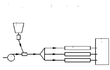
[0025] Example 1: figure 1 It is a dry selective non-catalytic reduction (Dry SNCR) method in which the reducing agent is urea powder in the present invention.

[0026] The dry selective non-catalytic reduction method in which the reductant is urea powder is: The urea granules are ground into urea powder and loaded into the silo; The urea powder is conveyed into the mixer through the feeder; The air from the conveying air source and the urea powder conveyed from the feeder are mixed in the mixer to form a mixed gas; The mixed gas is transported to the distributor through the pipeline, and the mixed gas is divided into multiple strands in the distributor; The mixed gas from the distributor is sent into the spray gun through the pipeline; The mixed gas is sprayed into the flue through the spray gun; The mixed gas participates in the denitrification reaction in the flue.

[0027] The device for realizing the present invention includes: a feed bin, a feeder, a conveyi...

Embodiment 2

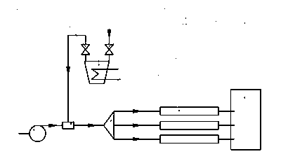
[0038] Example 2: figure 2It is a dry selective non-catalytic reduction (Dry SNCR) method in which the reducing agent of the present invention is ammonia gas, urea gas or urea melt. This dry selective non-catalytic reduction method is:

[0039] Liquid ammonia and urea are loaded into the heater through the feed valve to be heated and vaporized into ammonia gas and urea gas (or liquefied into urea melt); Ammonia gas, urea gas or urea melt enters the mixer through the discharge valve; The steam from the delivery gas source and the ammonia gas, urea gas or urea melt from the discharge valve are mixed in the mixer to form a mixed gas; The mixed gas is transported to the distributor through the pipeline, and the mixed gas is divided into multiple strands in the distributor; The mixed gas from the distributor is sent into the spray gun through the pipeline; The mixed gas is sprayed into the flue through the spray gun; The mixed gas participates in the denitrification r...


PUM


Abstract

The invention relates to a dry method selective non-catalytic reduction method and device, which belongs to the field of flue gas denitration. The method comprises the steps: smashing urea particles into urea powder or heating the urea particles to urea gas or heating and liquefyingthe urea particles to urea melt; or heating and gasifying liquid ammonia to ammonia; using urea powder, urea melt, urea gas or ammonia as a reducer, using air, flue gas or steam as a conveying medium, spraying the reducer to high temperature flue gas, and removing oxynitride in the flue gas. The denitration device of the method comprises a bunker, a feeder, an air source, a mixer, a distributor and a spray gun. The bunker is connected with the feed inlet of the mixer, the air source outlet is connected with an air inlet of the mixer, the feed outlet of the mixer is connected with the inlet of the distributor, and the outlet of the distributor is connected with the inlet of the spray gun. The invention is characterized in that the process is simple and reliable, and the operating cost is low; and the three deficiencies of large heat consumption, corrosion of water cooling wall and high fly ash content caused by gasifying aqueous solution by the wet method are overcome.

Description

technical field [0001] The invention relates to a flue gas denitrification method and device, in particular to a selective non-catalytic reduction denitrification method and device. Background technique [0002] Fossil fuel combustion is currently the main source of nitrogen oxide (NOx) pollutants. At present, flue gas denitrification mainly uses selective catalytic reduction (SCR) and selective non-catalytic reduction (SNCR) to remove nitrogen oxides. These two methods mainly use ammonia or urea as a reducing agent to reduce nitrogen oxides (NOx) to nitrogen and water. The selective non-catalytic reduction method is to spray reducing agents such as ammonia or urea into the flue gas at 850-1100 °C to achieve the reduction of nitrogen oxides (NOx). Since selective non-catalytic reduction does not use expensive, short-lived catalysts and does not require modification of the heating surface, it has been widely used. Urea is widely used as the preferred reducing agent for sele...

Claims


Application Information

Patent Timeline
Patent Type & Authority Applications(China)
IPC IPC(8): B01D53/79B01D53/56
Inventor 雍占锋刘远平张举乐高克迎吴树志
Owner 徐州燃烧控制研究院有限公司
Why Eureka
Try Eureka