

Electric grinding multi-line cutting current inlet method and device
A multi-wire cutting and electric grinding technology, applied in the direction of fine working devices, manufacturing tools, stone processing equipment, etc., can solve the problems of complex operation, cumbersome process methods, complex process methods, etc., to increase complexity and cost, The effect of simplifying the structure
- Summary
- Abstract
- Description
- Claims
- Application Information
AI Technical Summary
Problems solved by technology
Method used
Image

Examples
Embodiment 1
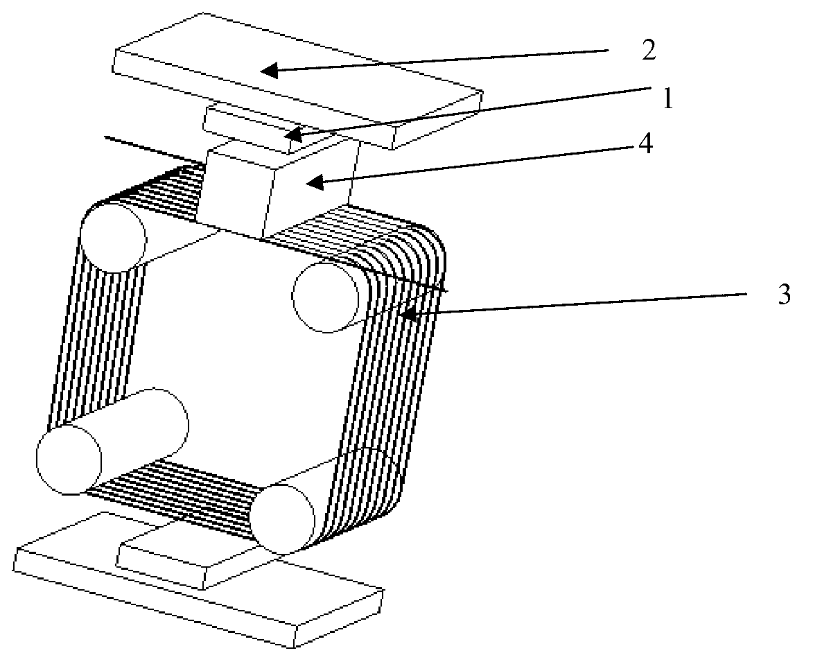
[0038] like Figure 1 ~ Figure 4 shown.
[0039] (1) Install the magnetic field generator 1 in the cutting room of the multi-wire cutting machine. The magnetic field generator 1 can be fixed by bolt connection or screw connection. The direction of the magnetic field can be set according to the actual situation. The purpose is to make the cutting line 3 When moving, induced electromotive force can be generated on both sides of the section of the cutting line 3 . In this embodiment, the direction of the magnetic field is perpendicular to the moving direction of the cutting wire 3 and parallel to the feeding direction of the cutting wire 3 . The applied magnetic field can be generated by permanent magnets or electromagnets, and the strength of the applied magnetic field can be adjusted to ensure that the induced electromotive force can be adjusted to cope with the processing of materials with different resistivities under the condition of constant wire speed. , In this embodime...
Embodiment 2
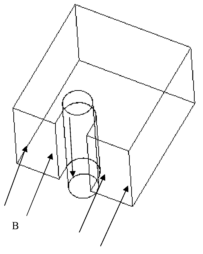
[0049] like Figure 5 and Figure 6 As shown, the difference from Embodiment 1 is that the direction of the magnetic field and the feeding direction of the cutting wire form an included angle of 45°.
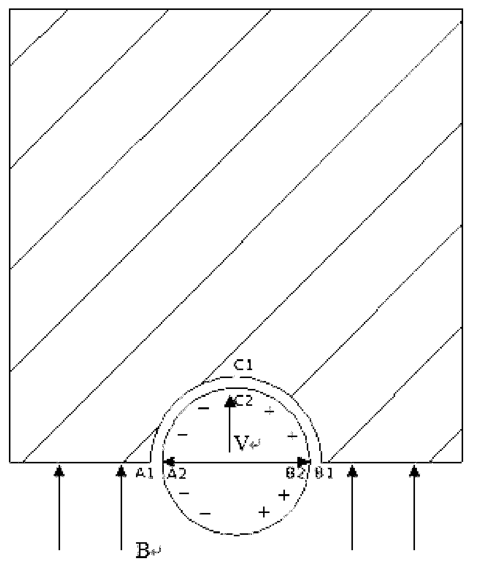
[0050] In this embodiment, the equivalent circuit diagram of the processing process is as follows Figure 6 shown.
[0051] Specifically, the area A1D1C1B1 is the workpiece to be processed, A2D2 is an area on the left of the cutting line, and B2C2 is an area on the right of the cutting line. The cutting line 3 moves inward along its axis perpendicular to the surface of the paper, an induced electromotive force is generated on the cutting line 3, B2C2 is the positive pole, and A2D2 is the negative pole. A1D1 and A2D2 contact each other through a very small gap to form a loop, and B1C1 and B2C2 also contact each other through a very small gap to form a loop. The A1D1 area is the anode of the electrochemical reaction, and the anode passivation occurs to form a passivation film....
Embodiment 3
[0055] The difference from Example 1 is that in this example, the diameter of the cutting line 3 is 100 μm, the linear speed of the cutting line 3 is 100 m / min, and the feed speed can be adjusted according to the processing conditions, and can be controlled between 200 and 500 μm / min; The composition of the cutting fluid: silicon carbide abrasive grains and polyethylene glycol in a mass ratio of 0.8:1, the particle size of the silicon carbide abrasive is controlled at less than 20 μm, and the flow rate of the cutting fluid is 100kg / min.
PUM
| Property | Measurement | Unit |
|---|---|---|
| Wire diameter | aaaaa | aaaaa |
Abstract
Description
Claims
Application Information