Cr-containing austenite alloy pipe and production method for same
A manufacturing method and technology of alloy pipes, applied in the direction of manufacturing tools, pipes, rigid pipes, etc., can solve problems such as period extension and economic loss
- Summary
- Abstract
- Description
- Claims
- Application Information
AI Technical Summary
Problems solved by technology
Method used
Image

Examples
Embodiment 1
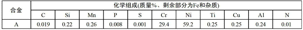
[0118] The blank pipe used for the experiment was manufactured by the following manufacturing method. First, alloys with chemical compositions shown in Table 1 were melted and cast to obtain steel ingots. After hot forging this steel ingot into a billet, it is formed into a pipe by a hot extrusion pipe-making method. The thus-obtained tube was cold-rolled using a cold pilger mill so that the outer diameter would be 25.0 mm and the wall thickness would be 1.65 mm. Next, the cold-rolled tube was annealed in a hydrogen atmosphere at 1100°C, and then finished by cold drawing to a product size of 19.0 mm in outer diameter, 1.0 mm in thickness, and 20,000 mm in length (reduction of area = 53%) the tube. Then, after cutting to a necessary length, the inner and outer surfaces of each tube were washed with an alkaline degreasing solution and flushing water, and the inner surface was further washed with acetone.
[0119] [Table 1]
[0120] Table 1
[0121]
[0122] While supplyi...
Embodiment 2
[0131] Next, as the influence of parameters, Cr-containing austenitic alloy pipes with different pipe diameters and pipe lengths were produced, and a chromium oxide film was formed under the conditions shown in Table 3 by the same method as in Example 1. The results are shown in Table 3.
[0132] [table 3]
[0133]
[0134] It can be seen from Table 3 that if the heat treatment conditions specified in the present invention are satisfied, the average film thickness of the obtained chromium oxide film is in the range of 0.05-1.5 μm, and the film thickness distribution also falls within the specified range. A Cr-containing austenitic alloy tube having a Cr oxide film having an appropriate film thickness range and distribution can be produced within the range of the tube inner diameter of 10 to 30 mm. Furthermore, regarding the influence of the tube length, by properly adjusting the water vapor concentration and the flow rate of the atmospheric gas, even a long tube of 30 m ca...
Embodiment 3
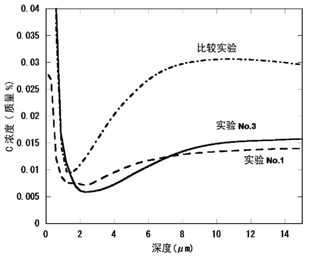
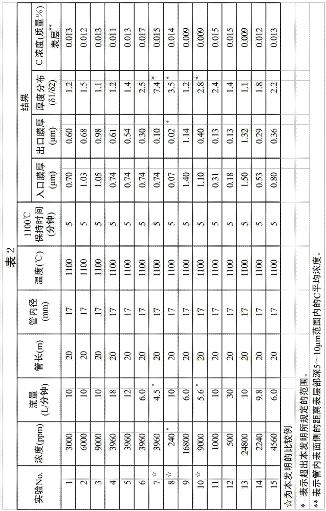
[0136] An alloy tube (tube length: 20 m, tube diameter: 17 mm) having the composition shown in Table 4 was oxidized with steam to form a chromium oxide coating. The conditions for film formation were as follows in Experiment No. 5: the hydrogen gas containing 3960 ppm water vapor was passed through the atmosphere gas at a flow rate of 12 L / min, the heat treatment temperature was 1100° C. and the treatment time was 5 minutes. Table 5 shows the measurement results of the film thickness and C concentration of the treated samples.
[0137] [Table 4]
[0138] Table 4
[0139]
[0140] [table 5]
[0141] table 5
[0142]
[0143] ** represents the average concentration of C in the range of 5 to 10 μm deep from the surface layer on the inner surface side of the tube.
[0144] Compared with Alloy A used in Examples 1 to 3, Alloys B, C, and D obtained substantially equivalent results in both thickness and distribution of coating films. In addition, it was confirmed that the ...
PUM
| Property | Measurement | Unit |
|---|---|---|
| length | aaaaa | aaaaa |
| diameter | aaaaa | aaaaa |
| length | aaaaa | aaaaa |
Abstract
Description
Claims
Application Information
 - R&D
- Intellectual Property
- Life Sciences
- Materials
- Tech Scout
- Unparalleled Data Quality
- Higher Quality Content
- 60% Fewer Hallucinations
Browse by: Latest US Patents, China's latest patents, Technical Efficacy Thesaurus, Application Domain, Technology Topic, Popular Technical Reports.
© 2025 PatSnap. All rights reserved.Legal|Privacy policy|Modern Slavery Act Transparency Statement|Sitemap|About US| Contact US: help@patsnap.com