DE-MZM automatic bias control device based on proportion integration differentiation (PID) and control method thereof

A DE-MZM, automatic bias technology, applied in the field of laser communication, can solve the problem that the bias control of the nonlinear point cannot be carried out, and it is only applicable to the modulator whose DC bias point is the minimum transmission point, etc., so as to achieve small error , Simple structure, easy to use

Inactive Publication Date: 2013-05-08
AIR FORCE UNIV PLA
View PDF2 Cites 28 Cited by
  • Summary
  • Abstract
  • Description
  • Claims
  • Application Information

AI Technical Summary

Problems solved by technology

[0003] However, the existing automatic bias control methods are mainly aimed at the modulator whose DC bias point is the linear point or the minimum transmission point, and cannot realize the bias control of all DC bias points of the electro-optical modulator. The main methods and shortcomings including the following aspects
Method 1 uses low-frequency disturbances for DC drift compensation. This method is only suitable for bias control of linear points and cannot be used for bias control of nonlinear points. Method 2 mixes and filters the input signal and feedback signal to obtain an error signal. The error signal controls the bias unit, which can realize the DC drift compensation of the coherent FSK system and the optically generated microwave local oscillator system, but it is only applicable to the modulator whose DC bias point is the minimum transmission point; method 3 uses the disturbance signal fundamental component and The amplitude ratio of the second harmonic component signal is used for automatic bias control of the modulator. Since the ratio has an infinite positive and negative mutation at the phase nπ, this method is not suitable for modulators whose bias points are 0 and π; method 4 is compared with The optical power before and after the modulator is used to realize the automatic control of the bias point. Since the gain of the two amplifiers needs to be adjusted in the error comparator to make the photocurrent before and after the modulation equal, and the optical power at the minimum transmission point is approximately zero, it is not suitable for the bias point of Modulator with Minimum Transmission Point

Method used


Image

  • DE-MZM automatic bias control device based on proportion integration differentiation (PID) and control method thereof
  • DE-MZM automatic bias control device based on proportion integration differentiation (PID) and control method thereof
  • DE-MZM automatic bias control device based on proportion integration differentiation (PID) and control method thereof

Examples


Embodiment 1

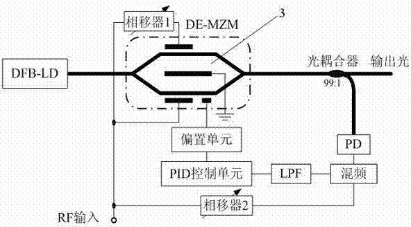
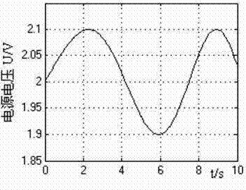
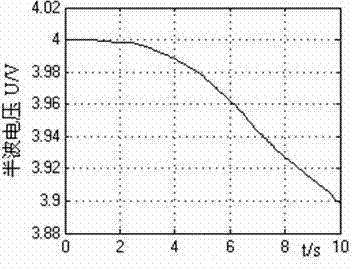
[0054] The random fluctuation of the bias unit power supply voltage and the change of the half-wave voltage of the electro-optic modulator will cause the DC bias point to drift. The constant superimposed chirp signal is used to simulate the random fluctuation of the bias unit power supply voltage, and its waveform is measured by the first oscilloscope. The monotonic decreasing signal generated by the constant superimposition signal generator simulates the change of the modulator half-wave voltage, and its waveform is measured by the second oscilloscope. The waveform constants of the two parts are selected as 2 and 4 respectively, which means that the DC bias phase is π / 2. The DC bias phase drift of the system without bias control Δ θ Measured by the third oscilloscope. The parameter of the PID controller is selected as K p =600, K i =10, K d =50, its output control signal is measured by the fourth oscilloscope. After feedback control, the output voltage of the bias unit is m...


PUM


Abstract

The invention discloses a DE-MZM automatic bias control device based on proportion integration differentiation (PID) and a control method thereof. In the DE-MZM automatic bias control device, a laser device is connected with an electrooptical modulator, one end of the electrooptical modulator is connected with one end of a phase shifter and one end of a optical coupler, the other end of the electrooptical modulator is connected with a bias unit and the phase shifter, the bias unit is connected with a control unit, the control unit is connected with a low pass filter, the low pass filter is connected with a mixer, the mixer is connected with a optical detector PD and one phase shifter, the phase shifter is connected with the other phase shifter, the optical detector PD is connected with the optical coupler, and the optical coupler outputs laser. Dual-electrode Mach-Zehnder modulator automatic bias control method with any direct current bias points enables error signals at different bias points to be identical in forms and kept close to a cosine function linear point by bringing in adjustable phase shifters, bias voltage of a modulator is adjusted automatically in high precision, so that the DE-MZM automatic bias control device is suitable for being applied in the electrooptical modulators with working modes of bilateral band modulation, unilateral band modulation, suppressed carrier modulation and low bias.

Description

technical field [0001] The invention relates to laser communication, in particular to a PID-based DE-MZM automatic bias control device and control method. Background technique [0002] Radio-over-Fiber (ROF) systems, which use optical fibers to transmit radio frequency signals, have increasingly become a research hotspot. In the ROF system, due to the influence of external environmental factors such as temperature and ionizing radiation, the half-wave voltage of the electro-optic modulator will change, and at the same time, the voltage of the DC bias power supply will also fluctuate randomly to a certain extent, causing the DC bias of the modulator Points drift, leading to system performance degradation. In order to improve the performance of the ROF communication system, it is necessary to effectively suppress the DC bias point drift phenomenon of the electro-optical modulator. [0003] However, the existing automatic bias control methods are mainly aimed at the modulato...

Claims


Application Information

Patent Timeline
Patent Type & Authority Applications(China)
IPC IPC(8): H04B10/516
Inventor 李勇军李轩朱子行谭庆贵幺周石蒋炜李瑞欣王建峰
Owner AIR FORCE UNIV PLA
Why Eureka
Try Eureka