
Magnetic fluid double-current generator

An AC/DC and generator technology, applied in the direction of electrical components, electromechanical devices, etc., to avoid seed recycling and pollution problems, improve conversion utilization, and reduce erosion

Inactive Publication Date: 2013-05-22
周华
View PDF6 Cites 11 Cited by
  • Summary
  • Abstract
  • Description
  • Claims
  • Application Information

AI Technical Summary

Problems solved by technology

But it is unrealistic to think about solving all the technical and material problems in magnetic fluid power generation in one go

Method used


Image

  • Magnetic fluid double-current generator
  • Magnetic fluid double-current generator
  • Magnetic fluid double-current generator

Examples


Embodiment 1

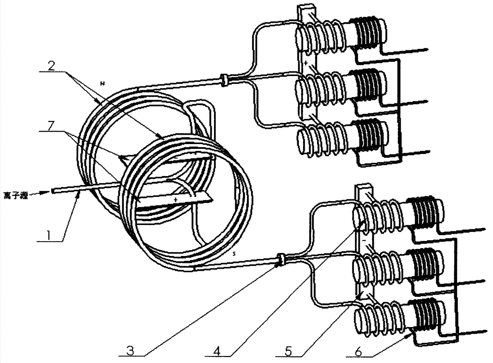
[0031] Such as figure 1 As shown, after the high-speed flowing conductive fluid is shunted by the magnetic field, the positive and negative ion flows respectively drive a set of generators to generate three-phase AC power generation. Through the phase adjustment of two three-phase sine wave four-way throttle valves 3, they can be connected in parallel and connected to the power grid. ; At the same time, the direct current output between the electrodes 5 can be converted into alternating current by the inverter and incorporated into the grid; The set heat exchanger can be used to preheat the working fluid and heat the steam to drive the steam turbine for secondary power generation.

Embodiment 2

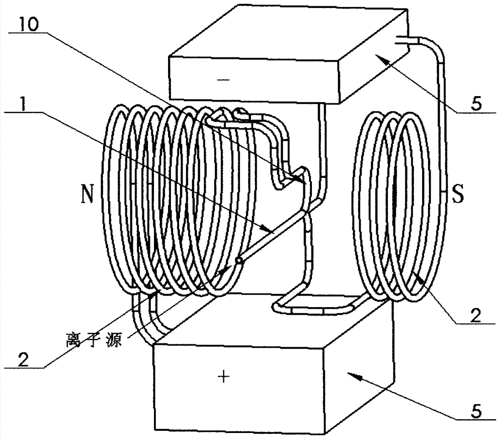
[0033] Such as image 3 As shown, the high-speed flowing conductive fluid returns to the magnetic field after being shunted by the magnetic field, and the positive ion flows through the secondary shunt tube 10. Separation is carried out according to the set pipeline, and the electrodes are decelerated and cooled at the electrode 5, and the electrons are recovered and collected separately. This embodiment can be used for pyrolysis hydrogen production or special metallurgy purification.

Embodiment 3

[0035] Such as figure 1 As shown, the output end of the generator coil 6 is connected to the squirrel-cage three-phase motor or the stator winding of the squirrel-cage three-phase motor is replaced by the ion flow coil 4. At this time, the system and the ion source constitute a motor, which can be applied to various kind of occasion.


PUM


Abstract

A magnetic fluid double-current generator mainly comprises a flow dividing tube (1), an ion current solenoid (2), a three-phase sine wave four-way throttle valve (3), an ion current coil (4), electrodes (5) and a power generation coil (6). The magnetic fluid double-current generator is characterized in that positive and negative ions of working mediums (come from plasma mixed gas or liquid of ion source) which flowed in high speed in the insulating flow dividing tube (1) are separated in a pipe constraint condition under the functions of electric field force or Lorentz force and respectively flow into the two electrodes (5) to achieve double-current power generation. The magnetic fluid double-current generator solves the problems that the existing magnetic fluid is low in converting efficiency of power generation energy, complex in structure, easy to corrode of electrodes, difficult to obtain the ultrastrong magnetic field, high in material requirements and only capable of generating electricity through direct current.

Description

1. Technical field: [0001] The invention relates to a magnetic fluid power generation device, which is a device for converting the internal energy of an ion source into electric energy, and even part of the energy can be converted into fuel chemical energy or mechanical energy. 2. Background technology: [0002] The principle of the existing magnetic fluid power generation: the plasma is injected into a power generation channel with a strong magnetic field at an ultra-high speed. The high-speed particles with positive and negative charges in the plasma are subjected to the Lorentz force in the magnetic field. The effect is to deviate respectively to two flat electrodes set perpendicular to the magnetic force lines and the direction of high-speed particle movement. The accumulated charge between the two poles generates a voltage, and the voltage is connected to the circuit with a wire to be used as a DC power generation or converted by an inverter. Into the electric field for...

Claims


Application Information

Patent Timeline
IPC IPC(8): H02K44/08
Inventor 周华
Owner 周华
Learn More