Thunder and lightening detector based on optics principle

A detection device and optical principle technology, applied in the field of lightning detection, can solve the problems of low azimuth measurement accuracy, susceptibility to electromagnetic interference, narrow measurement bandwidth, etc., and achieve the effects of rapid response, large measurement dynamic range and safe loading

Active Publication Date: 2013-06-05
CHINA ELECTRONIC TECH GRP CORP NO 38 RES INST
View PDF6 Cites 10 Cited by
  • Summary
  • Abstract
  • Description
  • Claims
  • Application Information

AI Technical Summary

Problems solved by technology

[0005] The invention provides a lightning detection device based on the optical principle, aiming to solve the problems of the traditional lightning measurement device, such as large volume, susceptibility to electromagnetic interference, narrow measurement bandwidth, low azimuth measurement accuracy, easy saturation in the measurement near the lightning channel, and the need for simultaneous Disadvantages such as equipped with power supply system and communication equipment

Method used


Image

  • Thunder and lightening detector based on optics principle
  • Thunder and lightening detector based on optics principle
  • Thunder and lightening detector based on optics principle

Examples


Embodiment 1

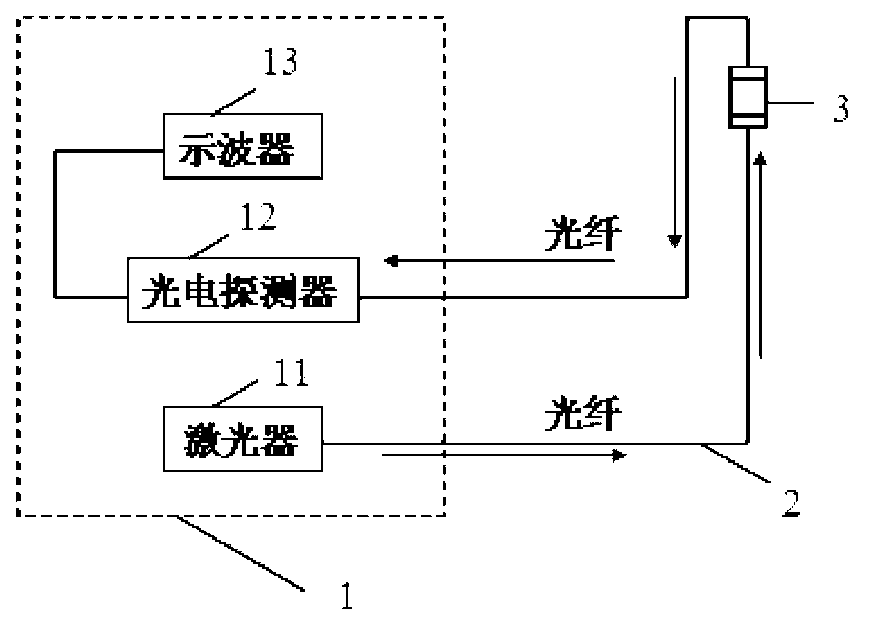
[0025] Such as figure 1 and figure 2 As shown, the lightning detection device based on the optical principle of the present invention includes a detection control center 1 , a transmission optical fiber 2 and a sensing probe 3 .

[0026] The detection control center 1 includes a laser 11 , a photodetector 12 , and a digital oscilloscope 13 .

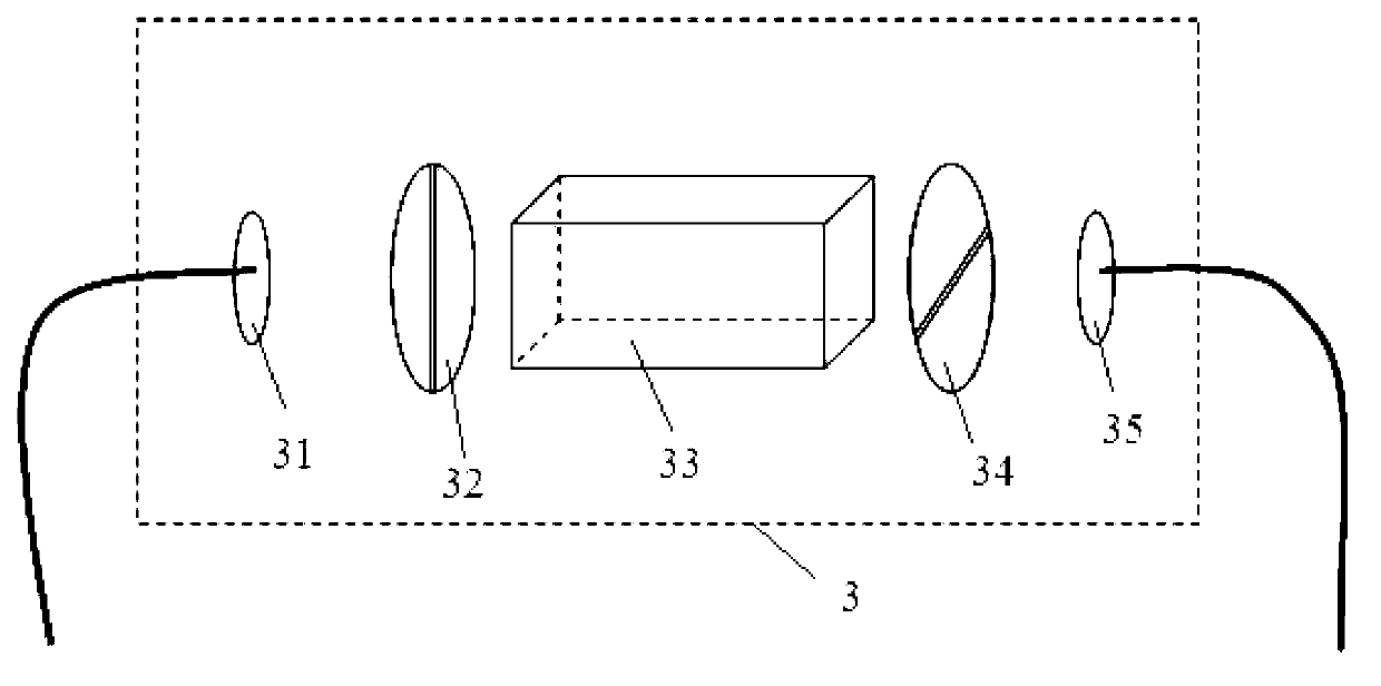
[0027] The sensing probe 3 includes a first collimating lens 31 , a polarizer 32 , an electro-optic / magneto-optic crystal 33 , an analyzer 34 , and a second collimating lens 35 .

[0028] The light generated by the laser 11 is transmitted to the sensor probe 3 through the transmission fiber 2, and the light first passes through the collimator lens 31 and then enters the polarizer 32, and under the action of the polarizer 32, it becomes aligned with the optical axis of the electro-optic / magneto-optic crystal 33. Linearly polarized light at an angle of 45 degrees, the electro-optic / magneto-optic crystal 33 is under the action of an elec...

Embodiment 2

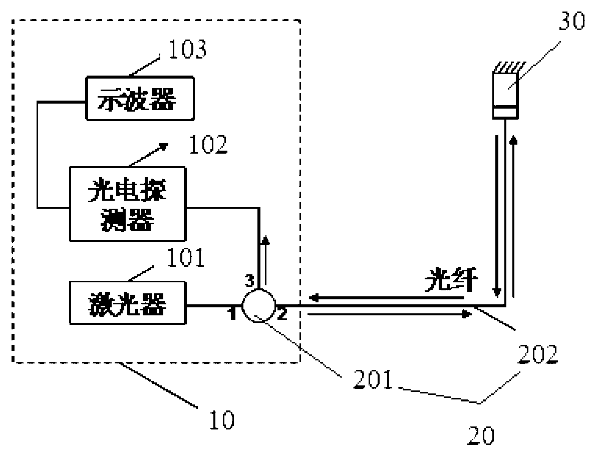
[0030] Such as image 3 and Figure 4 As shown, the lightning detection device based on the optical principle of the present invention includes a detection control center 10 , a transmission optical fiber 20 and a sensing probe 30 .

[0031] The detection control center 10 includes a laser 101 , a photodetector 102 , and a digital oscilloscope 103 .

[0032] The transmission optical fiber 20 includes an optical fiber 201 and an optical fiber circulator 202 .

[0033] The sensing probe 30 includes a collimator lens 301, a polarizer 302, an electro-optic / magneto-optic crystal 303, and a reflective film 304.

[0034] The light generated by the laser 11 is first transmitted to the sensor probe 30 through the 1-2 ports of the fiber optic circulator 202, and the light first enters the polarizer 302 through the collimating lens 301, and the polarization in the polarizer 302 becomes the same as that of the electro-optic / magneto-optic The optical axis of the crystal 303 is linearly ...

Embodiment 3

[0036] Such as Figure 5 and Figure 6 As shown, the lightning detection device based on the optical principle of the present invention includes a detection control center 100 , a transmission optical fiber 200 and a sensing probe 300 .

[0037] The detection control center 100 includes a laser 110 , a photodetector 120 , and a digital oscilloscope 130 .

[0038] Delivery fiber 200 includes fiber 210 .

[0039] The sensing probe 30 includes a collimating lens 310 , a polarizer 20 , an electro-optic / magneto-optic crystal 330 , and a corner reflector 340 .

[0040]The light generated by the laser 110 is first transmitted to the sensor probe 300 through the optical fiber 200, and the light first enters the polarizer 320 through the collimator lens 310, and the polarization in the polarizer 320 becomes 45° with the optical axis of the electro-optic / magneto-optic crystal 330 The linearly polarized light of angle, electro-optic / magneto-optic crystal 330 is under the effect of ele...


PUM


Abstract

The invention provides a thunder and lightening detector based on the optics principle. The thunder and lightening detector is formed by an optical link circuit and comprises a detection control center, optical fibers and a sensing probe. The detection control center comprises a laser unit, a photoelectric detector and a digital oscilloscope. Light emitted by the laser unit is transmitted to the sensing probe through the optical fiber. The sensing probe comprises an electric-light / magneto-optical crystal. The light is converted to linearly polarized light and then is propagated through two mutually-perpendicular linearly polarized light waves. The light emitted from the electric-light / magneto-optical crystal is converted from changes of the polarization state to changes of emergent light intensity and then is detected by the photoelectric detector. Signals detected in an electromagnetic field can be observed on the digital oscilloscope. The thunder and lightening detector based on the optics principle has the advantages that the sensing probe or an observation station of the thunder and lightening detector is completely formed by passive optical elements, and the thunder and lightening detector has the advantages of being small in size, light in weight, prompt in response, free from electromagnetic interference, large in measurement dynamic range, free from power supply and a communication system, and the like.

Description

technical field [0001] The invention relates to a lightning detection device based on an optical principle, which belongs to the technical field of lightning detection. Background technique [0002] When lightning occurs, a huge return current and electromagnetic pulse radiation will be generated. In addition to the hazards of direct lightning strikes, the thermal effects, electrodynamic effects, mechanical effects, shock wave effects, electrostatic induction effects, and electromagnetic field effects caused by lightning have increasingly seriously affected electric power, petrochemical, communication, transportation, aviation, micro The development of electronics and other industries. Especially in the military and aviation fields, lightning is more harmful, directly related to the safety of air vehicles, and is an important reference data for aircraft and spacecraft launch. Therefore, the safe production in various industries requires accurate detection and early warning...

Claims


Application Information

Patent Timeline
Patent Type & Authority Applications(China)
IPC IPC(8): G01R29/08
Inventor 贺胜男武帅
Owner CHINA ELECTRONIC TECH GRP CORP NO 38 RES INST
Why Eureka
Try Eureka