
A kind of preparation method of anode protection ring

An anode protection ring and electrolyte powder technology, applied in the field of aluminum electrolysis, can solve the problems of increasing the workload of carbon slag, increasing the energy consumption of electrolysis production, poor anti-oxidation performance, etc. The effect of high thermal shock performance

Active Publication Date: 2016-09-28
SNTO TECH GRP
View PDF4 Cites 0 Cited by
  • Summary
  • Abstract
  • Description
  • Claims
  • Application Information

AI Technical Summary

Problems solved by technology

This kind of protective ring has poor oxidation resistance and low compressive strength
Under the condition of high temperature in the electrolytic cell, if there is no insulation material covering, this kind of carbon protection ring is easily oxidized into pieces by the air, and falls into the electrolytic cell during the pole changing operation or under the scouring of the electrolyte solution. On the one hand, the anode steel claw Loss of protection will lead to the phenomenon of "claw melting", resulting in a decrease in the grade of primary aluminum; on the other hand, the oxidized carbon slag will fall into the electrolytic tank, which will increase the workload of workers to catch the carbon slag, increase the resistance of the tank, and increase the energy consumption of electrolytic production , in severe cases, even affect the life of the electrolyzer

Method used


Image

  • A kind of preparation method of anode protection ring
  • A kind of preparation method of anode protection ring
  • A kind of preparation method of anode protection ring

Examples


Embodiment 1

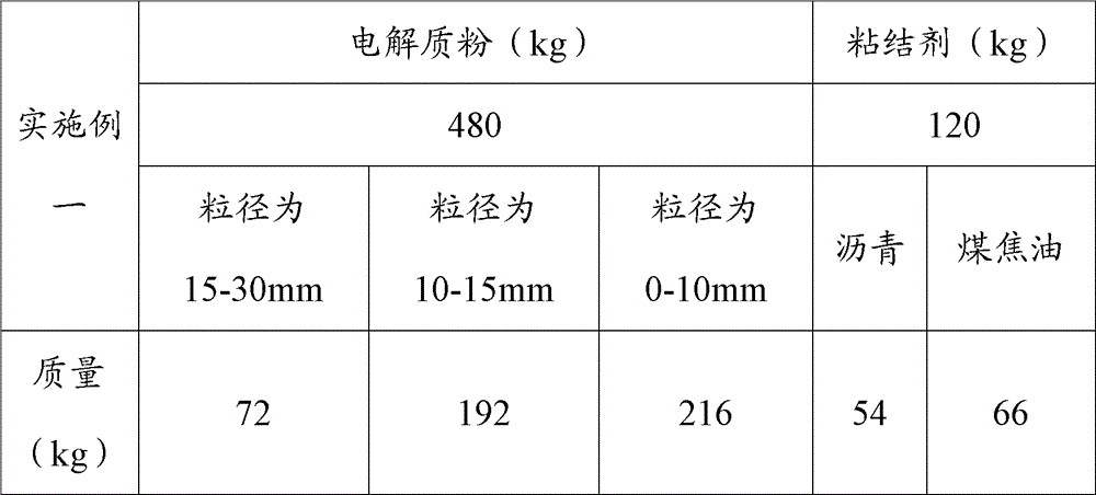
[0022] Crush the excess electrolyte with a crusher, grind the obtained powder with a ball mill for 1-3 hours, weigh 480kg of electrolyte powder (72g of electrolyte powder with a particle size greater than or equal to 15mm and less than or equal to 30mm, and a particle size of greater than or equal to 10mm and less than or equal to 15mm 192g of electrolyte powder, 216g of electrolyte powder with a particle size greater than 0mm and less than or equal to 10mm), 54kg of asphalt, and 66kg of coal tar; put the above raw materials into the kneading pot, raise the temperature to 85-130°C at the same time, and knead for 1 hour to form a slurry Then inject the slurry into the mold, put it into a hydraulic press for hydroforming, pressurize to 12-18MPa, and keep it for 15-35 seconds to obtain the anode protection ring. The mechanical strength of the prepared anode protection ring is much greater than that of ordinary carbon protection rings, and it has the advantages of abrasion resistan...

Embodiment 2

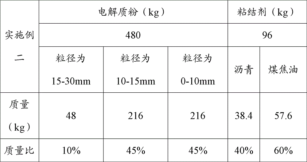
[0027] The steps of Embodiment 2 are the same as those of Embodiment 1, and the specific formula values ​​are shown in the table below, wherein the mass of the binder is 20% of the mass of the electrolyte powder:

[0028]

Embodiment 3

[0030] The steps of Embodiment 3 are the same as those of Embodiment 1, and the specific formula values ​​are shown in the table below, wherein the mass of the binder is 10% of the mass of the electrolyte powder:

[0031]


PUM

PropertyMeasurementUnit
particle diameteraaaaaaaaaa

Abstract

The invention discloses a preparation method of an anode protection ring. The method is characterized by comprising the following steps: milling an electrolyte block for 1-3h, making the ball-milled electrolyte pass through different screens to obtain electrolyte powders with different grain diameters, mixing and stirring the screened electrolyte powders with a bonder for 1h to form slurry, at the same time, raising the temperature to 85-130 DEG C, injecting the slurry into a mold, pressurizing the mold to 12-18MPa, and keeping for 15-35 seconds. The superfluous electrolyte is utilized to prepare the anode protection ring. During the process, the electrolyte is milled to a certain fineness, added with the bonder, and kneaded to mold, dried and baked to prepare the anode protection ring, thus the quality of the anode protection ring is improved, the waste from an electrolytic aluminum plant can be consumed, and the method is effective and environment-friendly.

Description

technical field [0001] The invention relates to the technical field of aluminum electrolysis, in particular to a method for preparing an anode protection ring. Background technique [0002] Usually, in aluminum electrolytic production, an anode protection ring is put on the connection between the anode steel claw and the anode carbon bowl, and the surface of the anode steel claw to isolate the anode steel claw and the electrolyte in the electrolytic cell, so as to protect the anode steel claw from being damaged. Electrolyte corrosion. [0003] At present, most of the anode protection rings are made of carbon materials and asphalt as a binder. They are formed by pressure machinery, and then put on the anode steel claws after drying. This kind of protective ring has poor oxidation resistance and low compressive strength. Under the condition of high temperature in the electrolytic cell, if there is no insulation material covering, this kind of carbon protection ring is easily...

Claims


Application Information

Patent Timeline
Patent Type & Authority Patents(China)
IPC IPC(8): C25C3/12B28B1/14
Inventor 不公告发明人
Owner SNTO TECH GRP
Learn More