Flue gas denitrification catalyst regeneration process and system device

A denitrification catalyst and process technology, applied in the field of flue gas denitrification, can solve the problems of increased production cost, labor and time, and long process flow, and achieve the effects of simplifying the regeneration process and operation steps, reducing the oxidation rate, and simplifying the process

Inactive Publication Date: 2015-08-19
深圳市水苑水工业技术设备有限公司
View PDF4 Cites 0 Cited by
  • Summary
  • Abstract
  • Description
  • Claims
  • Application Information

AI Technical Summary

Problems solved by technology

[0003] The existing catalyst regeneration process basically includes processes such as immersion, cleaning, activation, repair, and drying, and these five processes are divided into five independent units to complete, so more than 5 catalyst hoistings are required during the production process. The process is long, labor-intensive and time-consuming, which also increases production costs

Method used


Image

  • Flue gas denitrification catalyst regeneration process and system device
  • Flue gas denitrification catalyst regeneration process and system device
  • Flue gas denitrification catalyst regeneration process and system device

Examples


Embodiment 1

[0023] In the present embodiment, the process of the present invention comprises the following steps:

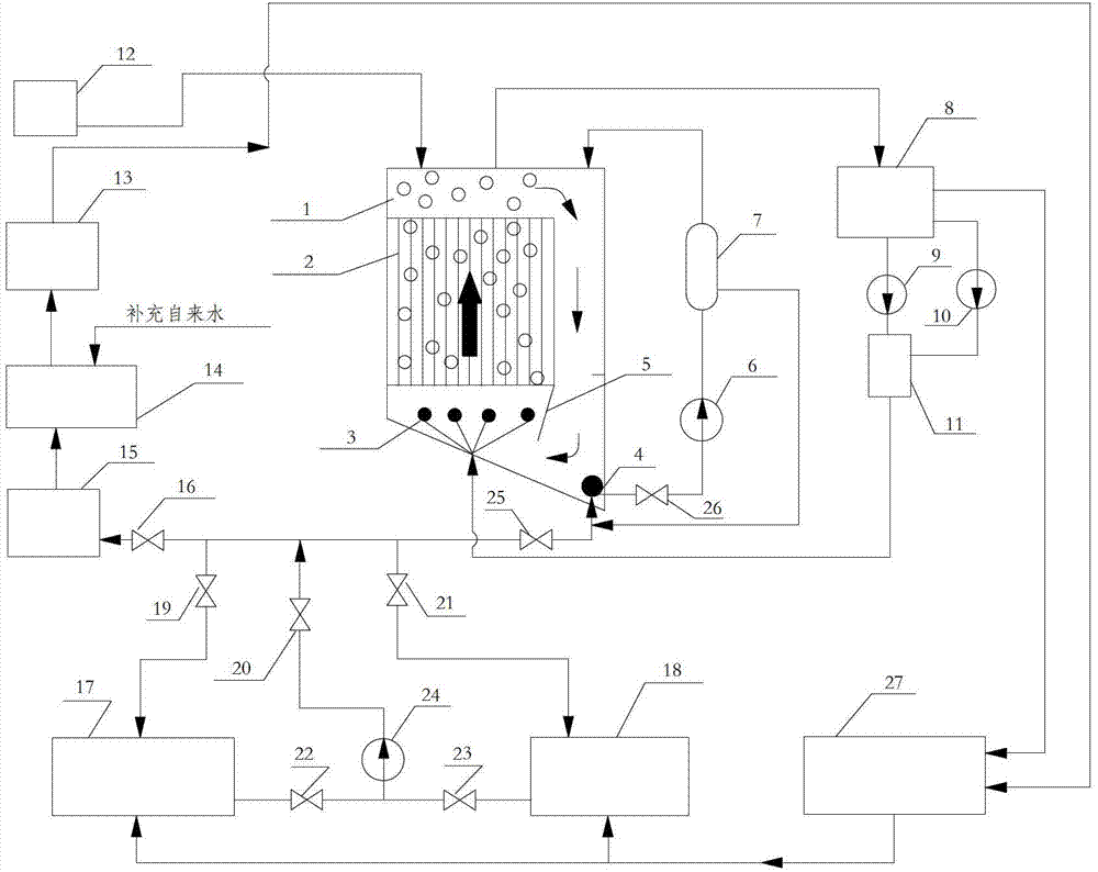
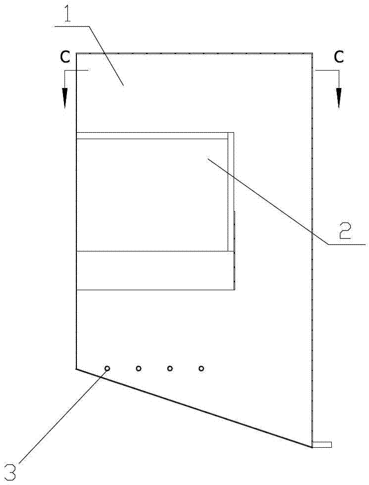
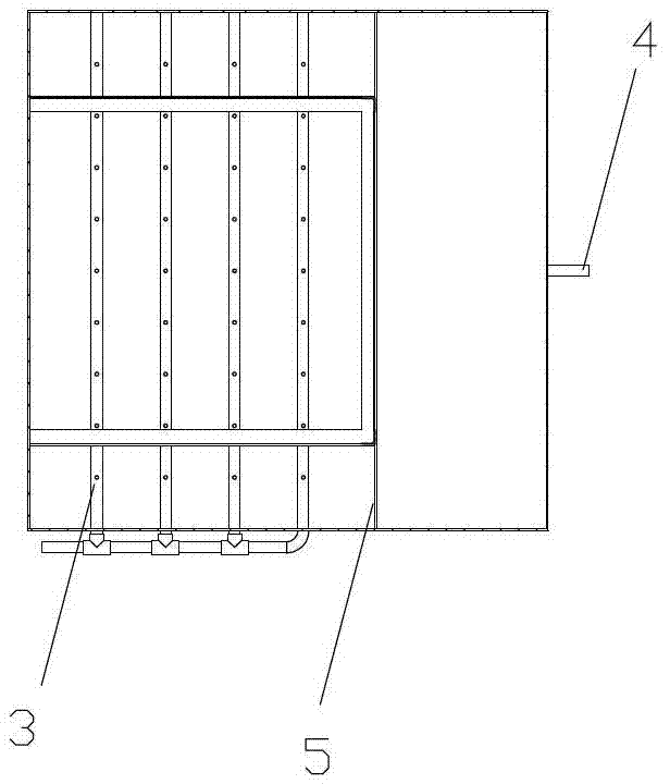
[0024] A: Cleaning of the denitrification catalyst: first put the regenerated denitrification catalyst 2 into the cleaning and activation pool 1, and then replenish the desalinated water to the cleaning and activation pool 1 through the desalinated water tank 27, the cleaning liquid storage tank 17 and the supplementary water pump 24 until the brine Submerge the catalyst 2, the concentration of brine used is:; through the dosing system 12, add the cleaning agent in sequence, the composition of the cleaning agent: polyacrylic acid 50mg / L, nonylphenol polyoxyethylene ether 50mg / L, fatty alcohol polyoxyethylene ether 200mg / L, sodium ascorbate 100mg / L, start the circulating fan 9, aeration pipe 3, circulating water pump 6 and filter 7 while adding the cleaning agent, the cleaning liquid circulates under the action of the aeration gas, mix evenly Add 1%wt of formic acid at the en...

Embodiment 2

[0031] In the present embodiment, the composition of the cleaning agent is polyacrylic acid 500mg / L, nonylphenol polyoxyethylene ether 700mg / L, fatty alcohol polyoxyethylene ether 1000mg / L, sodium ascorbate 500mg / L; 120°C; the composition of the activation solution: oxalic acid 500mg / L, ammonium metavanadate 120mmol / L, ammonium metatungstate 100mmol / L; citric acid 10%wt for pH control.

[0032] Other parts of this embodiment are identical to Embodiment 1.

Embodiment 3

[0034] The composition of cleaning agent described in this embodiment is polyacrylic acid 200mg / L, nonylphenol polyoxyethylene ether 400mg / L, fatty alcohol polyoxyethylene ether 600mg / L, sodium ascorbate 60mg / L; Control air temperature 80 °C; the composition of the activation solution: oxalic acid 300mg / L, ammonium metavanadate 80mmol / L, ammonium metatungstate 60mmol / L. Formic acid 5%wt for pH control.

[0035] Other parts of this embodiment are identical to Embodiment 1.


PUM


Abstract

The invention relates to a technique and a system device for regenerating exhaust gas denitration catalyst, and belongs to the technical field of exhaust gas processing of coal-fired power plant. The processing steps includes cleaning the denitration catalyst in a recirculation state and performing activation and dehydration on the denitration catalyst in the recirculation state. The detergent is composed of polyacrylic acid, nonylphenol polyoxyethylene ether, fatty alcohol-polyoxyethylene ether and sodium ascorbate; temperature is controlled at 40 DEG C; the activate fluid is composed of oxalic acid, ammonium metavanadate, ammonium metatungstate; and methane acid used for controlling PH value is 1% wt. The processes of soaking, cleaning, activating, dehydrating and the like for regenerating catalyst are integrated to implement in one container or two, so that volume of regeneration system is remarkably reduced, regeneration procedure and operation steps are simplified, energy consumption is reduced by 50%, and air pollution caused by exhaust gas is avoided.

Description

Technical field: [0001] The invention relates to a flue gas denitrification catalyst regeneration process and a system device, belonging to the technical field of smoke and dust treatment in coal-fired power stations, in particular to the technical field of flue gas denitrification. Background technique: [0002] In recent years, the nitrogen oxides (NO X ) emissions are on the rise. 2010 NO X Total emissions increased to 8.65 million tons. With the continuous expansion of the installed capacity of coal-fired power stations in my country, by 2015 and 2020 the NO X The total emissions will reach 11.16 and 12.34 million tons respectively. This poses a major threat to our environment and society. Since 2012, my country has formulated more stringent NO X Emission standard (100-200mg / m 3 ). Coal-fired power plants in densely populated areas have generally adopted the highly efficient flue gas denitrification technology-Selective catalytic reduction (Selective catalytic re...

Claims


Application Information

Patent Timeline
Patent Type & Authority Patents(China)
IPC IPC(8): B01J23/92B01J23/30C02F1/44C02F9/08
CPCY02A50/20
Inventor 胡仲英
Owner 深圳市水苑水工业技术设备有限公司
Why Eureka
Try Eureka