Through silicon via (TSV) back surface exposure process

A process, backside technology, applied in the field of microelectronics, can solve the problems of scratches, cracks, low efficiency and high cost

Active Publication Date: 2013-07-24
NAT CENT FOR ADVANCED PACKAGING
View PDF4 Cites 15 Cited by
  • Summary
  • Abstract
  • Description
  • Claims
  • Application Information

AI Technical Summary

Problems solved by technology

[0005] 1) In the prior art, the back of the wafer is directly thinned to the TSV conductive pillars by grinding. During the grinding process, conductive substances will be introduced into the surface of the wafer. The conductive substances may come from the abrasive contained in the abrasive Metallic substances or conductors inside TSV holes, such as copper ions, which will greatly reduce the minority carrier lifetime in the wafer substrate
[0006] 2) The traditional TSV outcropping method can easily cause mechanical damage to the head of the TSV conductive column, such as scratches, cracks, etc., which seriously affect the performance, reliability and yield of IC
[0007] 3) After the backside is thinned, a dielectric layer needs to be deposited, and the subsequent process

Method used


Image

  • Through silicon via (TSV) back surface exposure process
  • Through silicon via (TSV) back surface exposure process
  • Through silicon via (TSV) back surface exposure process

Examples


Embodiment 1

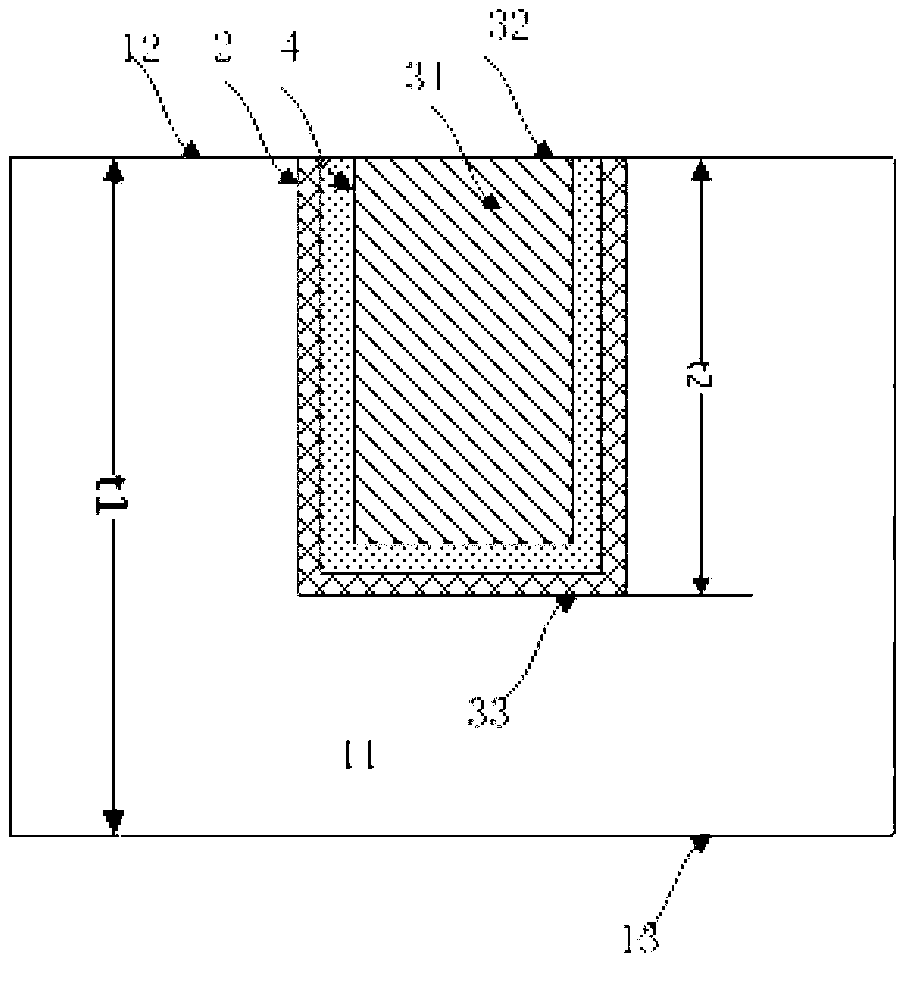
[0049] See Figures 2A-2G ,Should Figures 2A-2G It is a product structure diagram corresponding to each step in the first embodiment of the present invention. The meanings represented by the marks in the figure are as follows: 11 is the substrate (optionally, the substrate 11 is a silicon wafer (silicon wafer), silicon dioxide substrate (glass) or SiC), 12 is the front side of the substrate, 13 is the back side of the substrate, 2 is the dielectric layer (which can be silicon dioxide, silicon nitride or polymer), 31 is the TSV hole, 32 is the TSV hole, 33 is the bottom of the TSV hole (that is, the position of the subsequent outcrop), and 4 is Barrier layer (could be titanium, titanium nitride, tantalum or tantalum nitride, etc.). 51 is the dielectric protection layer (PI, BCB or POB, etc.), 52 is the final exposed TSV head, which can be directly interconnected with other devices, t1 is the initial thickness of the substrate, t11 is the thickness of the substrate after thin...

Embodiment 2

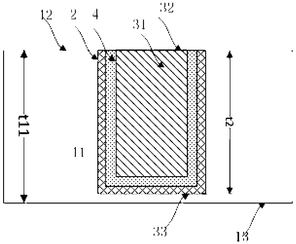
[0057] See Figures 3A-3F , Figures 3A-3F It is a device structure diagram corresponding to each step in the second embodiment of the present invention. The meanings of the marks in the diagram are as follows: 11 is the substrate (silicon wafer, glass, SiC), 12 is the front side of the substrate, 13 is the back side of the substrate, and 2 is the dielectric layer (which can be silicon dioxide, silicon nitride etc.), 31 is the TSV hole, 32 is the TSV hole, 33 is the bottom of the TSV hole (that is, the position of the subsequent outcrop), and 4 is the barrier layer (it can be titanium, titanium nitride, tantalum, tantalum nitride, etc.). 51 is the dielectric layer (PI, BCB, POB, etc.), 52 is the final exposed TSV head, which can be directly interconnected with other devices, etc., t1 is the initial thickness of the substrate, t11 is the thickness of the thinned substrate, and t12 is the second The substrate thickness after the first wet etching, t13 is the substrate thicknes...


PUM


Abstract

The invention discloses a through silicon via (TSV) back surface exposure process. By retaining a substrate above a TSV during the grinding of the back surface of the substrate, the damage to an exposed part of the TSV and the substrate caused by a physical thinning process is avoided, and the ground surface of the substrate with high total thickness variation (TTV) has high surface smoothness, so that the consistency in the subsequent etching process is high. The substrate is etched by an etching solution with high selection ratio of the substrate to a medium layer through a first wet method, the situation of etching of the medium layer and a barrier layer on the TSV for the first time decides whether or not the substrate is etched for the second time and the third time, the exposed part of the TSV has an enough height, and a conductive column of the exposed part is protected from being damaged by the etching solution. A photosensitive material serves as a medium protection layer, and a final TSV exposure structure is etched in an exposure and development manner, so that the corrosion and oxidization of conductive column copper in the conventional process are avoided, and the subsequent processing steps are simplified.

Description

technical field [0001] The invention relates to a method for manufacturing or processing semiconductor or solid devices or parts thereof in the technical field of microelectronics, in particular to a TSV outcropping process for transmitting current between separate components in a microelectronic device by using metal 3D interconnection. Background technique [0002] With the continuous advancement of microelectronics technology, the feature size of integrated circuits has been continuously reduced and the interconnection density has been continuously increased. At the same time, users' requirements for high performance and low power consumption continue to increase. In this case, the way to improve the performance by further reducing the line width of the interconnection is limited by the physical characteristics of the material and the equipment process, and the resistance-capacitance (RC) delay of the two-dimensional interconnection gradually becomes the limit to improve ...

Claims


Application Information

Patent Timeline
IPC IPC(8): H01L21/768
Inventor 张文奇王磊宋崇申王谆
Owner NAT CENT FOR ADVANCED PACKAGING
Why Eureka
Try Eureka