

Preparation method of thin-wall high-strength mold shell for single crystal blade manufacturing
A single crystal blade, high-strength technology, used in single crystal growth, manufacturing tools, casting and molding equipment, etc., can solve problems such as increased production costs and complex casting processes, and can improve thermal conductivity, reduce the number of mold shell layers, and have The effect of improving the temperature gradient
- Summary
- Abstract
- Description
- Claims
- Application Information
AI Technical Summary
Problems solved by technology
Method used
Image

Examples
Embodiment 1
[0021] 1. Shell making process
[0022] Different from ordinary investment precision casting mold shells, the mold shells used for directional solidification of single crystals not only need excellent high temperature strength, but also require strong heat dissipation performance of the mold shells. Therefore, low-density ceramic slurry and fine-grained sand are mainly used in shell making. The specific process flow is as follows.
[0023] (1) Slurry preparation, the slurry uses silica sol as binder (model: JN-30), high-purity corundum powder (Al 2 o 3 The content is greater than 99%, and the particle size is 320 mesh) is prepared as powder.
[0024] First, pour a certain amount of silica sol into the mixing tank, and the pouring amount is selected according to the required amount; then add a wetting agent (JFC, non-ionic surfactant) to ensure the coating and hangability of the slurry on the wax model. The amount added is about 0.1%-0.5% of the mass of silica sol; then cor...
Embodiment 2
[0058] 1. Molding process:
[0059] A 6-layer shell was prepared, and the slurry configuration, slurry coating, sand pouring, and slurry sealing process were the same as in Example 1, and the specific parameter requirements were shown in Table 4.
[0060] Table 4 shell making process parameters
[0061]
[0062] 2. Fiber coating drying process:
[0063] The prepared shell shape is the same as that in Example 1. After dewaxing and roasting, the fiber is wound and dried according to the process in Table 5. The obtained shell shape was applied to VDF-10 single crystal furnace for directional solidification, and single crystal samples have been successfully obtained.
[0064] Table 5 drying process parameters
[0065] Drying temperature / ℃ humidity / % Drying time / h Wind speed / m·s -1 25±5 ≤50 30-40 3-5
PUM
| Property | Measurement | Unit |
|---|---|---|
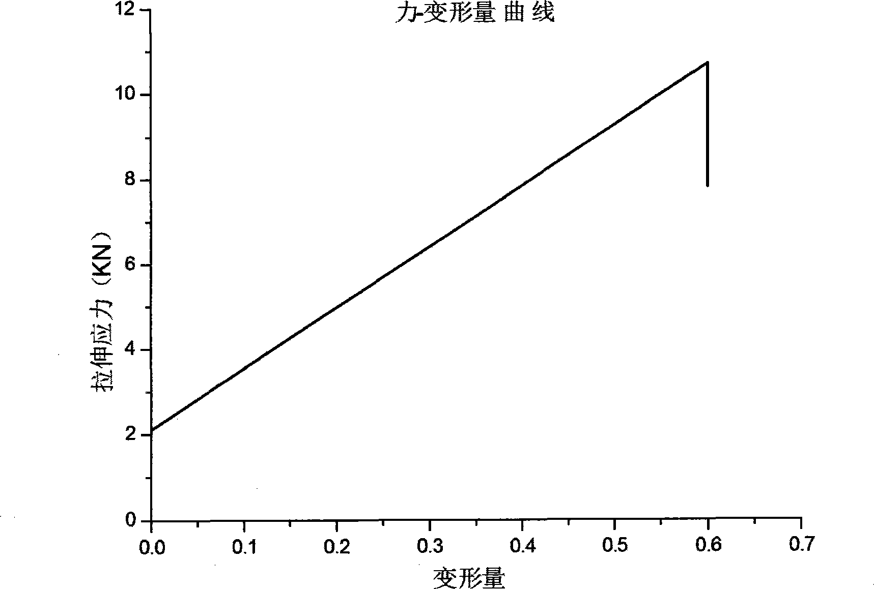
| tensile strength | aaaaa | aaaaa |
| particle size | aaaaa | aaaaa |
Abstract
Description
Claims
Application Information