Stimulated radiation loss micro imaging system

A technology of stimulated radiation loss and microscopic imaging, which is applied in the direction of material excitation analysis, fluorescence/phosphorescence, etc., can solve the problems of limited application range, influence, and greatly reduced experimental results, and achieves convenient and fast use, expanded application range, and high Effect of Optical Resolution

Active Publication Date: 2013-08-21
SUZHOU INST OF BIOMEDICAL ENG & TECH CHINESE ACADEMY OF SCI
View PDF7 Cites 34 Cited by
  • Summary
  • Abstract
  • Description
  • Claims
  • Application Information

AI Technical Summary

Problems solved by technology

[0004] However, the shortcomings of the lossy light generation method in the current STED microscope system are significant, mainly in two aspects: 1. The lossy light focal spot in the existing STED system is not good in theory, and the influencing factors of the lossy light focal spot This is because the beam is a vector beam composed of amplitude, phase, and polarization state. These three physical quantities of the vector beam will affect the distribution of the focal spot of the loss light. Current research often only studies the loss of light from one physical quantity. In this way, it is difficult to obtain a good focal spot distribution model of loss light in theory; second, static optical elements are used in the realization of loss light, and the scope of application of the STED super-resolution system is limited, such as the use of static vortex phase plates , the experimental effect will be greatly reduced when the experimental conditions change. This is because the vortex phase plate is only suitable for a narrow range of depleted light wavelengths. When the laser wavelength used for depleted light changes, a new vortex phase plate is required. Phase film

Method used


Image

  • Stimulated radiation loss micro imaging system
  • Stimulated radiation loss micro imaging system
  • Stimulated radiation loss micro imaging system

Examples


Embodiment Construction

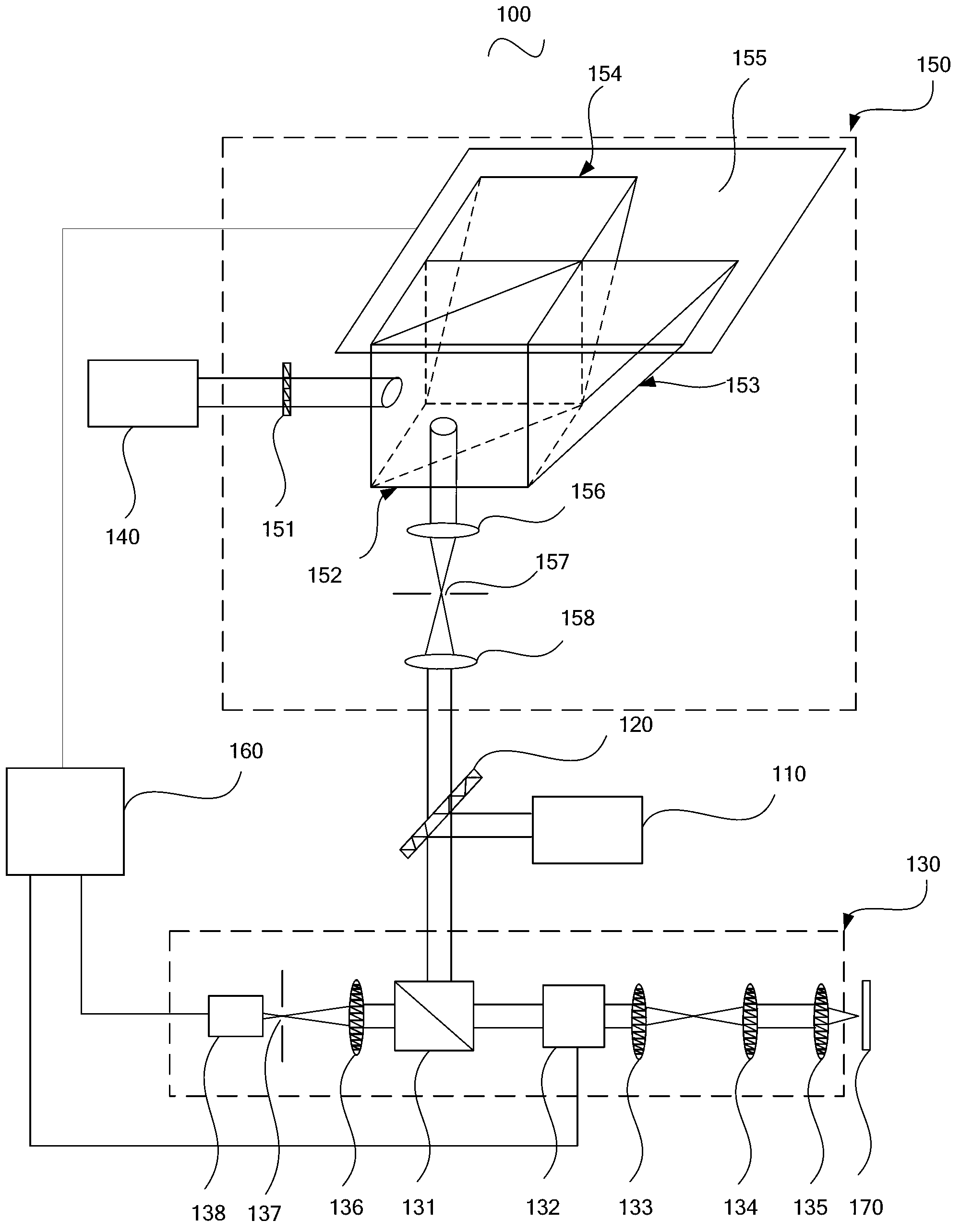
[0028] Please refer to figure 1 , figure 1 A schematic structural diagram 100 of a stimulated radiation depletion microscopy imaging system provided by an embodiment of the present invention.

[0029] The stimulated radiation depletion microscopy imaging system 100 includes an excitation laser 110 , a first dichromatic mirror 120 , a fluorescence excitation and imaging unit 130 , a depletion laser 140 , a vector beam modulation unit 150 and a control unit 160 .

[0030] The fluorescence excitation and imaging unit 130 includes: a second dichroic mirror 131 , an XY galvanometer scanning component 132 , a scanning lens 133 , a tube lens 134 , an objective lens 135 , an imaging lens 136 , a detection pinhole 137 and a photomultiplier tube 138 . Wherein, the detection pinhole 137 is located between the imaging lens 136 and the photomultiplier tube 138 and at the focal point of the imaging lens 136 .

[0031] The vector beam modulation unit 150 is used for modulating the amplitud...


PUM


Abstract

The invention provides a stimulated radiation loss micro imaging system which comprises an exciting light laser, a first dichroscope, a fluorescent light activating and imaging unit, a loss photoexcitation light, a vector beam modulation unit and a control unit, wherein the fluorescent light activating and imaging unit comprises a second dichroscope, an XY vibrating mirror scanning part, a scanning lens, a cylinder mirror, an objective lens, a probe hole and a photomultiplier tube. The stimulated radiation loss micro imaging system provided by the invention adopts the vector beam modulation unit to modulate the incident loss light laser beam amplitude, a phase and a polarization state, the loss light wave amplitude, the phase and the polarization state of the pupil of an objective lens are utilized to form loss light focal spots, and meanwhile, the loss light focal spots are reshaped in a fine and complicated manner under the action of the multiple physical quantities, so that the generated loss light focal spots are exactly matched with the exciting light focal spot distribution, meanwhile, the diameter of a centre dark region of the loss light focal spots is minimal under the condition of a certain signal-to-noise ratio, and the stimulated radiation loss micro imaging system has high optical resolution.

Description

technical field [0001] The invention relates to the field of design and manufacture of optical microscopic detection instruments, in particular to a stimulated radiation loss microscopic imaging system. Background technique [0002] Super-resolution optical microscopy has revolutionized research in the fields of biomedicine and materials science, and its research progress has had a profound impact in many scientific fields. Stimulated Emission Depletion (STED) microscopy is an optical super-resolution microscopy based on laser confocal microscopy. It is the far-field optics that was first proposed and most directly overcomes the optical diffraction limit. Microscopy, compared with other types of super-resolution microscopy, has relatively fast imaging speed, can image living cells, can detect finer structures in biomedical research, and also provides new methods for research in the field of materials science . The resolving power of STED super-resolution microscopy mainly ...

Claims


Application Information

Patent Timeline
Patent Type & Authority Applications(China)
IPC IPC(8): G01N21/64
Inventor 张运海张欣杨皓旻孔晨晖
Owner SUZHOU INST OF BIOMEDICAL ENG & TECH CHINESE ACADEMY OF SCI
Why Eureka
Try Eureka