Preparation method for micro-oil storage laser grid composite solid lubricating layer

A solid lubrication and meshing technology, which is applied in the direction of superimposed layer plating, solid diffusion coating, coating, etc., can solve problems such as wear and failure, and achieve the effects of high load bearing, reduced maintenance costs, and low friction coefficient

Inactive Publication Date: 2013-09-04
ACADEMY OF ARMORED FORCES ENG PLA +1
View PDF4 Cites 4 Cited by
  • Summary
  • Abstract
  • Description
  • Claims
  • Application Information

AI Technical Summary

Problems solved by technology

[0004] The purpose of the present invention is to provide a method for preparing a micro-oil storage laser grid composite solid lubricating layer, which can prepare a micro-oil storage laser network with a low friction coefficient and high wear resistance on the surface of mechanical equipment parts Grating composite solid lubricating layer to solve the problem of wear and failure of mechanical equipment parts due to poor lubrication in harsh environments, improve the reliability of mechanical equipment parts during service, prolong their service life, and reduce their maintenance costs

Method used


Image

  • Preparation method for micro-oil storage laser grid composite solid lubricating layer
  • Preparation method for micro-oil storage laser grid composite solid lubricating layer
  • Preparation method for micro-oil storage laser grid composite solid lubricating layer

Examples


preparation example Construction

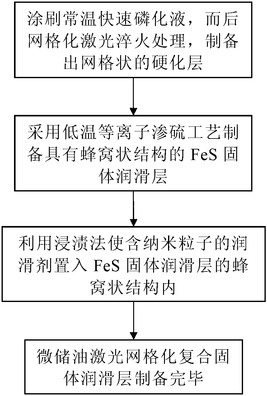
[0020] Such as figure 1 , the preparation method of the micro-oil storage laser grid composite solid lubricating layer of the present invention comprises the following steps:

[0021] Step 1: Brush the surface of the chromium molybdenum copper (CrMoCu) alloy cast iron of the mechanical equipment parts to be treated with a normal temperature rapid phosphating solution (known process liquid) that can speed up the laser quenching treatment speed, and wait for the normal temperature rapid phosphating solution After the liquid is dried, a gridded laser quenching treatment is carried out in a large laser processing system (a known processing system) to form a grid-like hardened layer on the surface of the chromium-molybdenum-copper alloy cast iron;

[0022] Step 2: using a low-temperature plasma sulfurizing process on high-frequency pulse plasma sulfurizing equipment (known equipment), and preparing a FeS solid lubricating layer with a honeycomb structure on the surface of the harde...

Embodiment

[0034] First, degrease and derust the surface of the chromium-molybdenum-copper alloy cast iron of the mechanical equipment parts to be treated, and then brush the normal temperature rapid phosphating solution on the surface of the chromium molybdenum copper alloy cast iron. After the normal temperature rapid phosphating solution dries, Gridded laser quenching treatment is carried out in a large laser processing system. The process parameters are: laser output power 350W, laser scanning speed 40mm / s, laser spot diameter 1.5mm, grid units are prepared on the surface of chrome-molybdenum-copper alloy cast iron A hardened layer with a diamond shape and a thickness of 0.45 mm.

[0035] Then, the low-temperature plasma sulfurizing process is adopted on the high-frequency pulse plasma sulfurizing equipment. The process parameters are: use sulfur vapor, working voltage 750V, working pressure 150Pa, sulfurizing temperature 210°C, holding time 2h, so that the surface of the hardened lay...


PUM

PropertyMeasurementUnit
thicknessaaaaaaaaaa
thicknessaaaaaaaaaa
particle diameteraaaaaaaaaa

Abstract

The invention discloses a preparation method for a micro-oil storage laser grid composite solid lubricating layer. The method comprises the following steps. Room-temperature quick phosphating solution is painted on the surface of chromium, molybdenum, and copper alloy cast iron of mechanical equipment parts to be processed. After the room-temperature quick phosphating solution is dried, grid laser-quenching treatment is carried out. A gridded hardened layer is formed on the surface of the chromium, molybdenum, and copper alloy cast iron. A FeS solid lubricating layer with a honeycomb structure is prepared on the hardened layer by the low-temperature plasma sulfurizing technology. Nanoparticle-containing lubricant is loaded in the honeycomb structure of the FeS solid lubricating layer by the impregnation method and therefore the micro-oil storage laser grid composite solid lubricating layer is finished. The micro-oil storage laser grid composite solid lubricating layer is advantaged by low friction coefficient, high abrasion resistance and high load carrying capacity. The micro-oil storage laser grid composite solid lubricating layer can raise the reliability of mechanical equipment parts, extend the service life and reduce the maintenance cost.

Description

technical field [0001] The invention relates to a method for preparing a micro-oil storage laser gridded composite solid lubrication layer, which belongs to the technical field of anti-wear lubrication (solid lubrication, nano lubrication and oil lubrication) of mechanical equipment parts. Background technique [0002] Friction phenomena widely exist in metallurgy, mining, building materials, electric power, machinery, agricultural machinery, national defense, aviation, aerospace and other industries. The friction pairs in mechanical equipment parts, such as gears and gears, shafts and bearings, piston rings and cylinder liners, usually inevitably produce friction and wear when they are in contact with the working environment and external media. Wear is one of the three major failure modes of materials. 80% of mechanical equipment parts are damaged and 40% of maintenance costs are caused by wear, and 1 / 3 of energy is consumed in overcoming friction. Therefore, effectively c...

Claims


Application Information

Patent Timeline
Patent Type & Authority Applications(China)
IPC IPC(8): C23C28/04C23C22/05C23C22/82C23C8/36
Inventor 乔玉林赵海朝赵玉强臧艳崔庆生
Owner ACADEMY OF ARMORED FORCES ENG PLA
Why Eureka
Try Eureka