Metal chloride gas generator, hydride vapor phase epitaxy growth apparatus, and method for fabricating a nitride semiconductor template

A gas generating device, chloride technology, applied in the direction of semiconductor devices, chemical instruments and methods, from chemically reactive gases, etc., can solve the problems of difficulty in making good-quality templates, mixed impurities, etc., to achieve suppression of optical waveguide phenomenon, Effect of suppressing mixing of impurities

Inactive Publication Date: 2013-09-25
SUMITOMO CHEM CO LTD
View PDF8 Cites 8 Cited by
  • Summary
  • Abstract
  • Description
  • Claims
  • Application Information

AI Technical Summary

Problems solved by technology

However, when the template is partially grown by the HVPE method that can reduce the manufacturing cost, many unwanted impurities are mixed in, and it is currently difficult to produce a good quality template

Method used


Image

  • Metal chloride gas generator, hydride vapor phase epitaxy growth apparatus, and method for fabricating a nitride semiconductor template
  • Metal chloride gas generator, hydride vapor phase epitaxy growth apparatus, and method for fabricating a nitride semiconductor template
  • Metal chloride gas generator, hydride vapor phase epitaxy growth apparatus, and method for fabricating a nitride semiconductor template

Examples


no. 1 Embodiment approach

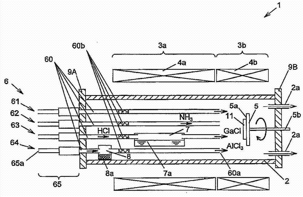
[0055] figure 1 It is a diagram showing a schematic configuration example of the HVPE apparatus according to the first embodiment of the present invention. This HVPE apparatus 1 is divided into an upstream raw material part 3a and a downstream growth part 3b, and is heated to about 850°C and 1100°C by respective raw material part heaters 4a and growth part heaters 4b, respectively.

[0056] In addition, in the HVPE device 1, there is a cylindrical reaction furnace 2, the open end of the upstream side of the reaction furnace 2 is closed by an upstream side flange 9A made of SUS, and the open end of the downstream side of the reaction furnace 2 is made of SUS. The downstream side flange 9B is closed. Further, through the upstream side flange 9A, from the raw material part 3a toward the growth part 3b, four doping pipes 61, a group V pipe 62, a group III (Ga) pipe 63, and a group III (Al) pipe 64 are provided. The gas supply pipeline 6 of each system.

[0057] (Structure of g...

no. 2 Embodiment approach

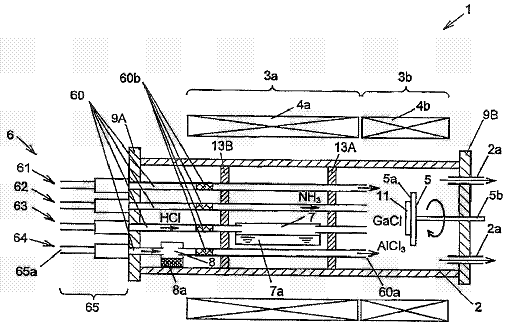
[0075] image 3 It is a diagram showing a schematic configuration example of an HVPE apparatus according to a second embodiment of the present invention. This embodiment is an HVPE apparatus obtained by adding the first and second heat shield plates 13A and 13B to the HVPE apparatus 1 of the first embodiment, and the other configurations are the same as those of the first embodiment.

[0076] That is, in the HVPE apparatus 1 of the present embodiment, the first heat shield plate 13A is disposed between the growth portion 3b having the highest temperature and the raw material portion 3a in the reaction furnace 2, and the upstream flange 9A is shielded from the first heat shield plate 13A. The second heat shield plate 13B is arranged between the plates 13A. By arranging the first and second heat shield plates 13A, 13B, the radiant heat from the growth portion 3b can also be suppressed, and the temperature near the gas introduction port 65a (upstream side end portion 65) of the ...

no. 3 Embodiment approach

[0079] Figure 4 It is a diagram showing a schematic configuration example of an HVPE apparatus according to a third embodiment of the present invention. This embodiment is an HVPE apparatus in which the installation surface 5a of the disk 5 is arranged so as to be horizontal with respect to the flow direction of the raw material gas in the HVPE apparatus 1 of the first embodiment, and the other configurations are the same as those of the first embodiment. It is configured to rotate the disk 5 by changing the power transmission direction of the rotary shaft 5 b by 90° through a bevel gear not shown or the like.

[0080] Also in this embodiment, it is possible to suppress the mixing of unwanted impurities similarly to the first embodiment. In addition, by arranging the installation surface 5 a of the disc 5 so as to be horizontal with respect to the flow direction of the source gas, it is easy to uniformize the film thickness in the plane.


PUM

PropertyMeasurementUnit
wavelengthaaaaaaaaaa

Abstract

The invention provides a metal chloride gas generator, a hydride vapor phase epitaxy growth apparatus, and a nitride semiconductor template, wherein undesirable impurities are prevented from mixing with the raw materials of the nitride semiconductor template. An hydride vapor phase epitaxy (HVPE) growth apparatus comprises a Ga tank and an A1 tank both arranged at a raw material section on an upstream side, and a growing section reacting furnace provided with a growth sapphire substrate. A raw material section heater and a heater each of which heats an inside of the reactor, an upstream end comprising a gas inlet, and a gas inlet pipe arranged to extend from the upstream end via the receiving section to the growing section, for introducing a chloride gas from the upstream end to supply the chloride gas to the receiving section and supplying a metal chloride gas produced by a reaction between the chloride gas and the metal in the receiving section to the growing section. The gas inlet pipe includes a suppressing section for suppressing an optical wave guiding phenomenon which waveguides a radiant heat from the growing section heater or the growing section.

Description

technical field [0001] The invention relates to a metal chloride gas generating device, a hydride vapor deposition device and a method for manufacturing a nitride semiconductor template. Background technique [0002] Group III nitride semiconductors such as gallium nitride (GaN), aluminum gallium nitride (AlGaN), and indium gallium nitride (InGaN) have attracted attention as light-emitting element materials capable of emitting light from red to ultraviolet. One of these nitride semiconductor crystal growth methods is a hydride vapor phase deposition method (HVPE: Hydride Vapor Phase Epitaxy) using metal chloride gas and ammonia as raw materials. [0003] As the characteristics of the HVPE method, it is listed that it is possible to obtain several micrometers typical of other growth methods (MOVPE: Metal-Organic Vapor Phase Epitaxy, Molecular Beam Epitaxy (MBE: Molecular Beam Epitaxy)). The growth rate per hr is significantly larger than that of 10 μm / hr or more to 100 μm / hr...

Claims


Application Information

Patent Timeline
Patent Type & Authority Applications(China)
IPC IPC(8): C23C16/34C23C16/448H01L33/00
CPCC30B25/14C30B25/02C30B25/16C30B29/403
Inventor 今野泰一郎藤仓序章
Owner SUMITOMO CHEM CO LTD
Why Eureka
Try Eureka