Cleaning method and cleaning device

A cleaning device and autoclave technology, applied to cleaning methods and appliances, cleaning devices for processing textile materials, chemical instruments and methods, etc., can solve problems such as low critical temperature and safety, achieve shedding suppression, improve cleaning efficiency, and economically excellent effect

Active Publication Date: 2013-10-02
YKK CORP +1
View PDF7 Cites 7 Cited by
  • Summary
  • Abstract
  • Description
  • Claims
  • Application Information

AI Technical Summary

Problems solved by technology

In addition, in Patent Document 1, it is described that alkane (ethane, propane, or pentane), ammonia, carbon dioxide, carbon monoxide, and nitrous oxide are used alone or in combination as a solvent to become a supercritical fluid. Starting from low and operational safety, etc., the use of carbon dioxide is generally being studied

Method used


Image

  • Cleaning method and cleaning device
  • Cleaning method and cleaning device
  • Cleaning method and cleaning device

Examples


Embodiment 1

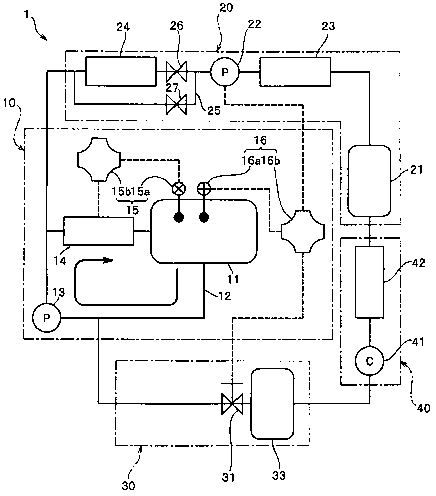
[0140] Prepare a tape-shaped fiber product made of polyester fiber, with respect to the fiber product, use figure 1 The cleaning device 1 is shown for dyeing.

[0141] In the dyeing process, first, a fiber product is wound in 11 layers on one bobbin, and the bobbin is accommodated in the autoclave 11 . In addition, a red dye (C.I. Disperse Red 22) is accommodated in the autoclave 11 together with fiber products. Next, the supply pump 22 is driven to supply supercritical carbon dioxide from the storage tank 21 to the circulation path 12 via the supply pump 22 and the preheating unit 24 . Simultaneously, the circulation pump 13 is also driven to circulate the supercritical carbon dioxide in the circulation path 12 and the autoclave 11 .

[0142] And while circulating supercritical carbon dioxide, the temperature in the autoclave 11 was raised to 125° C. by the temperature control unit 15, and the pressure in the autoclave 11 was increased to 25 MPa by the pressure control uni...

Embodiment 2

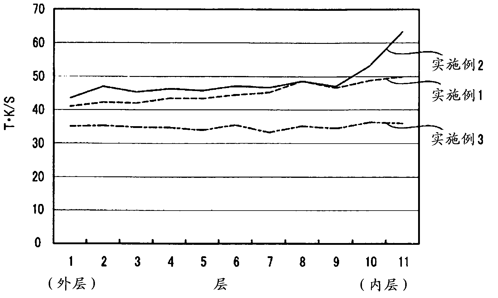
[0147] In Example 2, in the washing process, except that the temperature drop rate in the autoclave 11 was controlled at 10.83°C / min, the dyeing and washing of the fiber product were carried out in the same manner as in the above-mentioned Example 1. deal with. After that, the total K / S of the obtained fiber product and the color difference ΔE of each layer were calculated. CMC(2:1) .

Embodiment 3

[0149] In Example 3, the dyeing and washing of the fiber product were carried out in the same manner as in Example 1 above, except that the temperature in the autoclave 11 was lowered at a rate of 1.10°C / min during the washing process. deal with. After that, the total K / S of the obtained fiber product and the color difference ΔE of each layer were calculated. CMC(2:1) .

[0150] Here, for the above-mentioned fiber products of Examples 1 to 3, the results of calculating the total K / S are shown in image 3 , In addition, the color difference ΔE of each layer will be obtained CMC(2:1) The result expressed in Figure 4 . In addition, in image 3 and Figure 4 In the graph, the horizontal axis represents each layer of the fiber product when the fiber product is wound on the bobbin. On the horizontal axis, the outermost layer of the wound fiber product is the first layer, and the innermost ( center side) is the 11th floor.

[0151] After cleaning the fiber products of Exampl...


PUM


Abstract

Provided is a cleaning method for cleaning a product which is contained in an autoclave (11) and is dyed by circulating a fluid in a supercritical state in which dye is dissolved and the autoclave (11) after the dyeing is terminated, the cleaning method being characterized in that after the dyeing is terminated, a pure fluid in the supercritical state which does not contain the dye is continuously introduced into the autoclave (11), thereby gradually reducing the concentration of the dye in the fluid in the supercritical state which exists in the autoclave (11) to perform the cleaning continuously. As a result, it is possible to effectively clean the product and the autoclave (11) with the supercritical fluid while suppressing precipitation of the dye dissolved in the supercritical fluid, and significantly improve the cleaning efficiency because the cleaning process is performed continuously from the dyeing process.

Description

technical field [0001] The present invention relates to a cleaning method and a cleaning device for cleaning the fiber product and the autoclave after dyeing the fiber product in an autoclave with a fluid in a supercritical state (supercritical fluid). Background technique [0002] Conventionally, when dyeing textile products, a large amount of water was used as a dyeing medium. However, problems such as water resource conservation and waste liquid treatment have been pointed out, and the development of dyeing technology with a lower load on the environment has been demanded. Therefore, in recent years, a method of using a supercritical fluid as a dyeing medium has been proposed as a dyeing method in which the discharge amount of waste liquid is very small compared with the past. [0003] For example, Japanese Patent No. 3954103 (Patent Document 1) discloses a dyeing device and a dyeing method for dyeing fiber products with a supercritical fluid. [0004] Such as Figure 5 ...

Claims


Application Information

Patent Timeline
Patent Type & Authority Applications(China)
IPC IPC(8): D06P7/00B08B7/00
CPCB08B7/0021C11D11/0017D06P5/02D06L1/00D06B5/22D06B19/00D06B23/22D06B23/30D06P1/94D06B9/06Y02P70/62
Inventor 上野清隆井出贵睦斋藤崇桥爪贵宏
Owner YKK CORP
Why Eureka
Try Eureka