
Graphene auxiliary brazing method for ceramic matrix composite material and metal material

A technology of composite materials and metal materials, applied in the field of graphene-assisted brazing of ceramic matrix composite materials and metal materials, can solve the problems of poor mechanical properties of welded joints, achieve high-quality connections, relieve residual stress, and improve mechanical effects

Active Publication Date: 2013-10-09
HARBIN INST OF TECH
View PDF8 Cites 40 Cited by
  • Summary
  • Abstract
  • Description
  • Claims
  • Application Information

AI Technical Summary

Problems solved by technology

[0005] The purpose of the present invention is to provide a graphene-assisted brazing method for ceramic matrix composite materials and metal materials in order to solve the problem of poor mechanical properties of welded joints obtained by brazing existing ceramic matrix composite materials and metal materials

Method used

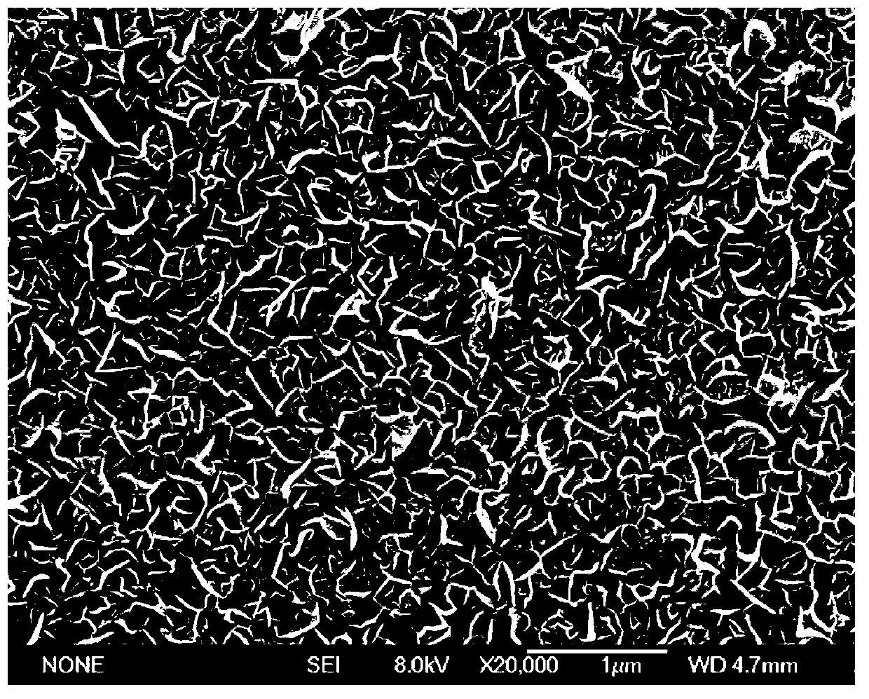
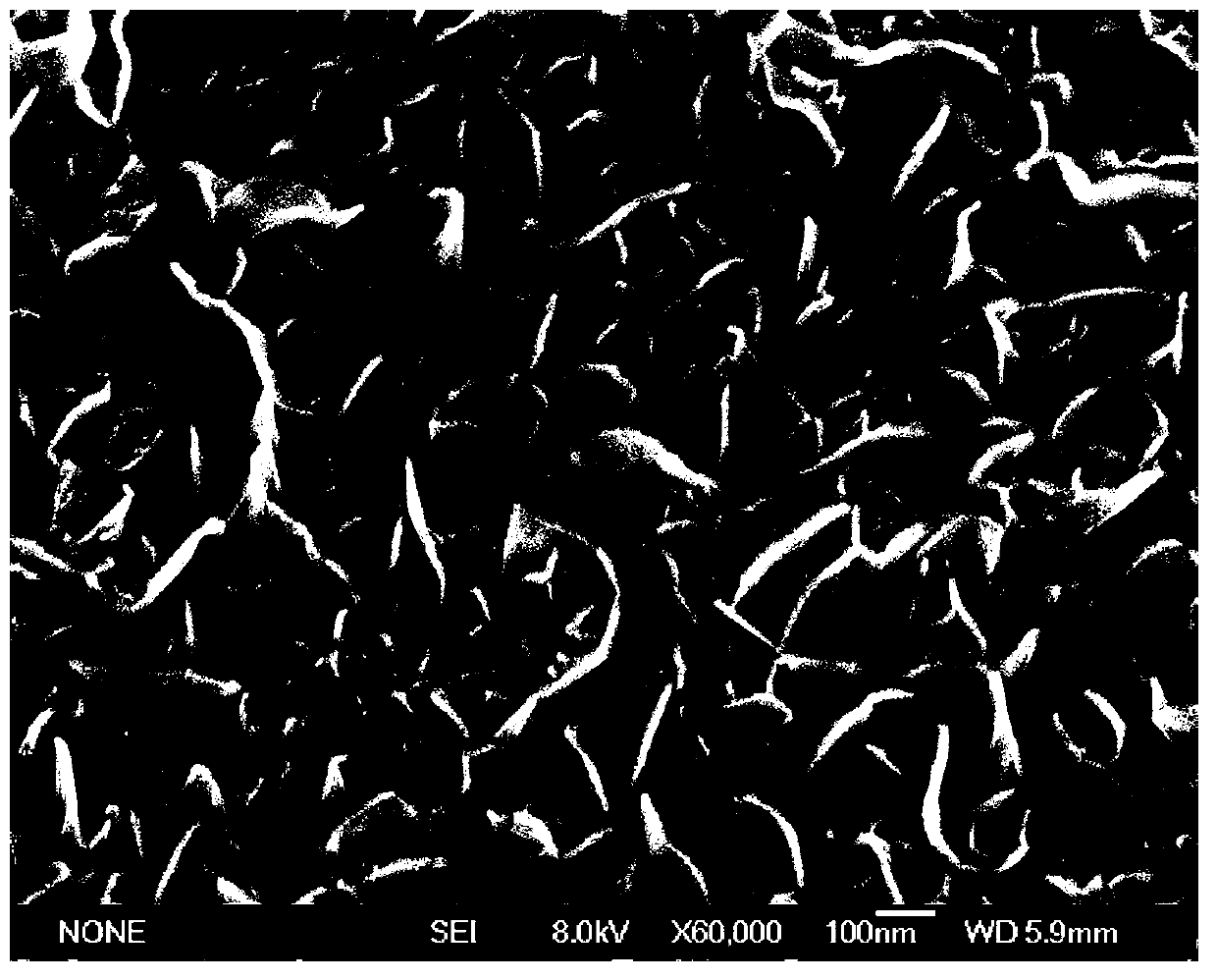
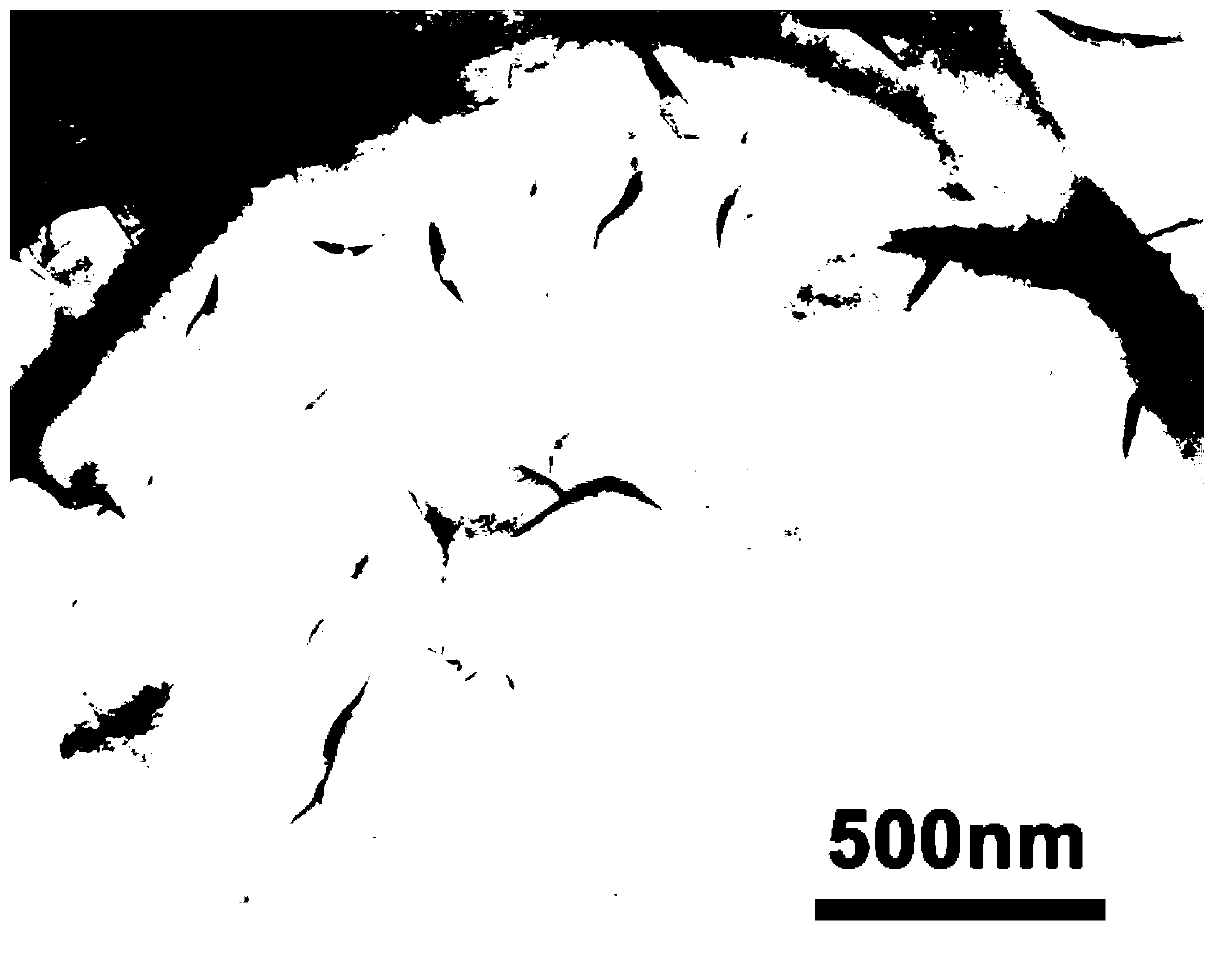

Image

  • Graphene auxiliary brazing method for ceramic matrix composite material and metal material
  • Graphene auxiliary brazing method for ceramic matrix composite material and metal material
  • Graphene auxiliary brazing method for ceramic matrix composite material and metal material

Examples


specific Embodiment approach 1

[0019] Specific implementation mode one: the graphene-assisted brazing method of ceramic matrix composite material and metal material in this implementation mode is realized according to the following steps:

[0020] 1. Put the ceramic matrix composite material into the plasma-enhanced chemical vapor deposition equipment, evacuate to below 5Pa, and pass in the protective gas H 2 and Ar gas, adjust the H 2 The flow rate is 10-50sccm, the Ar flow rate is 10-50sccm, the protective gas pressure is 100-500Pa, and then the working temperature is raised to 500-1000°C. After reaching the working temperature, turn on the RF power supply, adjust the RF power to 200W, and process for 10-30min Perform plasma surface treatment;

[0021] 2. After the surface treatment is finished, turn off the RF power supply and switch on CH 4 Gas, Regulated CH 4 The flow rate is 10-50sccm, the Ar flow rate is 50-100sccm, adjust and maintain the working pressure at 100-500Pa, turn on the RF power supply...

specific Embodiment approach 2

[0024] Specific embodiment two: the difference between this embodiment and specific embodiment one is that the ceramic matrix composite material is SiO 2 ceramic matrix composites, Si 3 N 4 Ceramic matrix composites, SiC ceramic matrix composites, quartz fiber woven ceramic matrix composites or SiC fiber reinforced ceramic matrix composites. Other steps and parameters are the same as those in Embodiment 1.

specific Embodiment approach 3

[0025] Embodiment 3: This embodiment is different from Embodiment 1 or Embodiment 2 in that the metal material is metal niobium, titanium alloy or Invar alloy. Other steps and parameters are the same as those in Embodiment 1 or Embodiment 2.


PUM

PropertyMeasurementUnit
shear strengthaaaaaaaaaa

Abstract

A graphene auxiliary brazing method for a ceramic matrix composite material and a metal material elates to a brazing method for the ceramic matrix composite material and the metal material and solves the problem that a brazed connector obtained by brazing the ceramic matrix composite material and the metal material is poor in mechanical property. The brazing method comprises the steps of placing the ceramic matrix composite material into plasma reinforcing chemical vapor deposition equipment to carry out plasma surface treatment, adding CH4 gas to regulate flow, opening a radio frequency power supply, regulating the radio frequency to deposit for 10-30min, using Ar and H2 as protection gas, cooling to the room temperature, obtaining the ceramic matrix composite material with graphene growing on the surface, placing Ti brazing filler metal between faces to be connected, placing the Ti brazing filler metal into a vacuum brazing furnace to be brazed, and finally cooling to the room temperature to finish brazing. The shear strength of a connector formed by the ceramic matrix composite material and the metal material in the brazing method can reach to 35Mpa at the room temperature.

Description

technical field [0001] The invention relates to a brazing method of a ceramic matrix composite material and a metal material. Background technique [0002] Ceramic matrix composites have high strength and stiffness, relatively light weight, excellent high temperature resistance and high temperature corrosion resistance, and good chemical stability, and have broad application prospects in aviation, aerospace, automotive and other fields. However, ceramic matrix composites have low plasticity and poor formability, making it difficult to use them alone. In practical applications, connection technology is often used to make composite components of ceramic matrix composite materials and metal materials, such as nozzles and combustion chambers of rocket engines, turbine engine parts of space shuttles, etc. Therefore, the connection between ceramic matrix composites and metal materials has gradually become a key issue restricting the use of this material. [0003] At present, the...

Claims


Application Information

Patent Timeline
Patent Type & Authority Applications(China)
IPC IPC(8): B23K1/008B23K1/20
Inventor 亓钧雷万禹含张丽霞曹健冯吉才
Owner HARBIN INST OF TECH
Learn More