
Method and device for processing oxidized tail gas of anthraquinone process-based hydrogen peroxide production

A technology for oxidizing tail gas and hydrogen peroxide, applied in the direction of peroxide/peroxy hydrate/peroxyacid/superoxide/ozonide, chemical instruments and methods, combined devices, etc., can solve the problem of decreased adsorption capacity of activated carbon fibers , the circulating water volume and temperature are not easy to control, and the recovery function decays quickly, etc., to achieve the effect of being conducive to comprehensive utilization, not easy to freeze, and meeting environmental protection

Inactive Publication Date: 2013-10-30
湖南双阳高科化工有限公司
View PDF4 Cites 13 Cited by
  • Summary
  • Abstract
  • Description
  • Claims
  • Application Information

AI Technical Summary

Problems solved by technology

[0003] At present, the cooling method of oxidation exhaust gas generally adopts low-temperature water, also called ice machine method, which directly uses the cooling capacity generated by the ice machine to produce low-temperature water, and then uses low-temperature water to exchange heat with the exhaust gas in the oxidation exhaust cooler to cool the exhaust gas for recovery. Among them, the aromatic hydrocarbons, the ice machine needs to consume a certain amount of energy during the operation process, the operation cost is high, the circulating water volume and temperature are not easy to control during the operation process, and production failures are prone to occur
The activated carbon fiber adsorption device uses the adsorption of activated carbon fibers to aromatics and the desorption of steam to recover aromatics. The recovery rate is high, but a certain amount of steam is consumed, and activated carbon fibers need to be replaced regularly. In addition, after its treatment The recovered aromatics need to be distilled and refined in the preparation process before returning to the system for use. When the content of aromatics in the tail gas is high, the recovery function of the activated carbon fiber adsorption device will decay rapidly during operation, resulting in a decrease in the adsorption capacity of activated carbon fibers.

Method used


Image

  • Method and device for processing oxidized tail gas of anthraquinone process-based hydrogen peroxide production

Examples


Embodiment 1

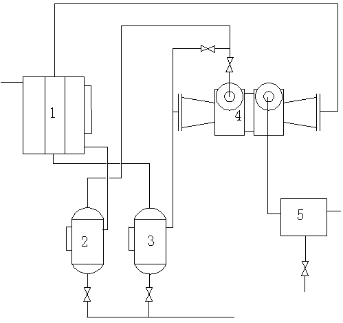
[0021] Example 1: The oxidation tail gas at 20°C first passes through the heat exchanger 1 for heat exchange; after the oxidation tail gas is cooled to 5°C, it enters the first gas-liquid separation tank 2 for gas-liquid separation; from the top of the first gas-liquid separation tank 2 The discharged uncondensed gas then enters the expansion chamber of the turbo expander 4, and is cooled by the turbo expander 4 for capacity expansion and cooling. After cooling down to 0°C, it enters the second gas-liquid separation tank 3 for gas-liquid separation; from the second gas-liquid separation The uncondensed gas discharged from the top of the tank 3 is heat-exchanged through the heat exchanger 1; after being heated to 6°C, it enters the turbo expander 4 for compression and boosting; the pressure is raised to 0.05MPa, the temperature is 15°C, and then enters the activated carbon adsorption device 5.

Embodiment 2

[0022] Example 2: The oxidation tail gas at 40°C first passes through the heat exchanger 1 for heat exchange; after the oxidation tail gas is cooled to 15°C, it enters the first gas-liquid separation tank 2 for gas-liquid separation; from the top of the first gas-liquid separation tank 2 The discharged uncondensed gas then enters the expansion chamber of the turbo expander 4, and is cooled by the turbo expander 4 to perform work and cooling. After cooling down to 5°C, it enters the second gas-liquid separation tank 3 for gas-liquid separation; from the second gas-liquid separation The uncondensed gas discharged from the top of the tank 3 is heat-exchanged through the heat exchanger 1; after being heated to 20°C, it enters the turbo expander 4 for compression and boosting; the pressure is raised to 0.1MPa, the temperature is 40°C, and then enters the activated carbon adsorption device 5.

Embodiment 3

[0023] Example 3: The oxidation tail gas at 30°C first passes through the heat exchanger 1 for heat exchange; after the oxidation tail gas is cooled to 10°C, it enters the first gas-liquid separation tank 2 for gas-liquid separation; from the top of the first gas-liquid separation tank 2 The discharged uncondensed gas then enters the expansion chamber of the turbo expander 4, and is cooled by the turbo expander 4 to expand the capacity and cool down. After cooling down to 2.5°C, it enters the second gas-liquid separation tank 3 for gas-liquid separation; from the second gas-liquid separation The uncondensed gas discharged from the top of the tank 3 is heat-exchanged through the heat exchanger 1; after being heated up to 8°C, it enters the turbo expander 4 for compression and boosting; the pressure is raised to 0.08MPa, the temperature is 28°C, and then enters the activated carbon adsorption device 5.


PUM


Abstract

The invention discloses a method and a device for processing oxidized tail gas of anthraquinone process-based hydrogen peroxide production. The device comprises a heat exchanger (1), a first gas-liquid separation tank (2), a second gas-liquid separation tank (3), a turbo-expander (4) and an activated carbon adsorption apparatus (5), wherein the second gas-liquid separation tank (3), the turbo-expander (4) and the activated carbon adsorption apparatus (5) are interconnected through a pipeline; the oxidized tail gas firstly performs heat exchange through the heat exchanger (1); the cooled oxidized tail gas enters into the first gas-liquid separation tank (2), then the non-condensed gas exhausted from the first gas-liquid separation tank (2) enters into an expansion cavity of the turbo-expander (4), after being cooled under expansion work, the gas enters into the second gas-liquid separation tank (3), and the non-condensed gas exhausted from the second gas-liquid separation tank (3) enters into the heat exchanger (1) to perform heat exchange; after being heated up, the gas enters into the turbo-expander (4) to be compressed and pressurized, then, the gas enters into the activated carbon adsorption apparatus (5); the arene separated from the liquid-gas separation tanks and the activated carbon adsorption apparatus (5) is recycled.

Description

technical field [0001] The invention belongs to the technical field of anthraquinone production of hydrogen peroxide, and relates to an energy-saving and emission-reduction method and device in the oxidation process, in particular to a recovery method for anthraquinone production of hydrogen peroxide oxidation tail gas; the invention also relates to an anthraquinone Production of hydrogen peroxide oxidation tail gas recovery device. Background technique [0002] The development of hydrogen peroxide production methods has roughly experienced three development stages: electrolysis, nickel catalyst stirred tank hydrogenation process anthraquinone method and palladium catalyst fixed bed hydrogenation process anthraquinone method. At present, palladium catalyst fixed bed hydrogenation The anthraquinone method of the process is the main production method. With the increasing attention of the society on energy conservation and emission reduction and the increasingly fierce market ...

Claims


Application Information

Patent Timeline
IPC IPC(8): B01D50/00B01D53/04C01B15/023
Inventor 张永泽赵涸浜李卫红
Owner 湖南双阳高科化工有限公司
Learn More